MFJ-259C Instruction Manual HF/VHF SWR Analyzer
5
3.) Frequency Counter Input: BNC connector used for frequency-counter functions only.
3.2 Power-up Display
After turning on the Power switch (or after applying external power with the switch on), a sequence of three message
screens appear on the display.
The first screen presents the analyzer's software version (VER).
The second message shows the software copyright symbol.
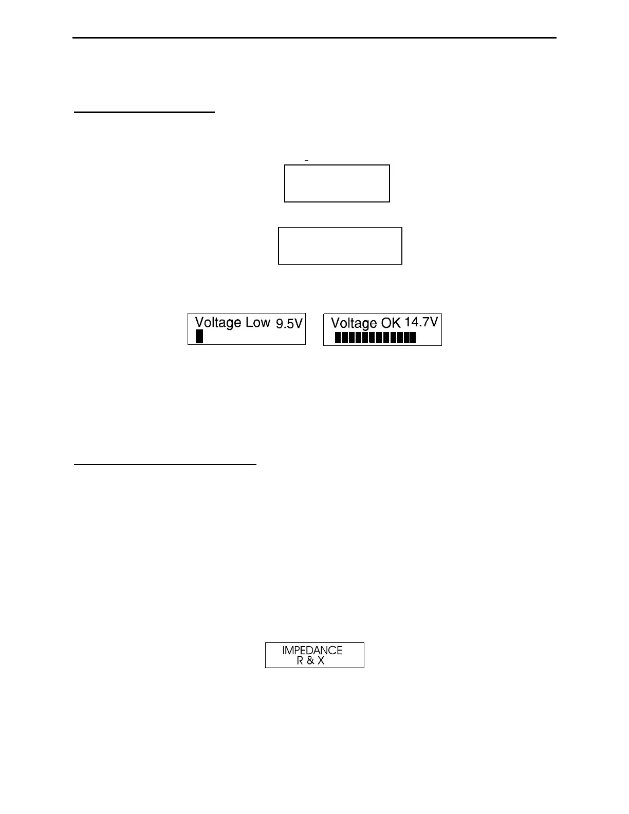
The third message provides a power-source check, displaying the internal battery or external power supply voltage
level along with a warning if the source is too low to support reliable operation.
The fourth and final power-up display is the working screen for the analyzer’s default operating mode, as described
in Section 3.2 (SWR, Impedance R&X). The two analog panel meters also become active, displaying SWR and
Impedance Magnitude (Z) measurements for the DUT.
The MFJ-259D has five (5) Basic Operating Modes that are used for conducting a variety of measurements. If you
tap (momentarily press) the Mode button, the analyzer steps to the next Mode selection. The five main modes and
their opening screens are described in Section-3.3 below:
3.3 Main MODE descriptions
Press the Mode switch to scroll through the analyzer's five operating modes. By "scrolling", we mean that each tap of
the mode switch will step the analyzer ahead to the next menu selection. Each new selection comes up on the display
with an Identifier Screen. After 3 seconds, the Identifier Screen is replaced by the mode's working screen. The menu
is circular, so after sequencing through all five choices, the sequence starts over. The five basic operating modes are
described in detail below:
1.) Impedance R&X (Initial Mode): Use this mode for measuring SWR and complex impedance. The Impedance
R&X mode is the analyzers "default" mode because it is the one most frequently used for routine antenna
adjustments. The top line of the working display shows the VFO Frequency in MHz and the numerical SWR
reading. The lower line displays the Resistive (R) and Reactive (X) impedance components for the attached load.
Pressing and holding the Gate button in this mode displays the Impedance Magnitude (Z) and Phase Angle (Ø).
The analog Impedance meter also displays Impedance Magnitude (Z), and the SWR meter displays Standing
Wave Ratio (SWR). The analog meters are especially useful when tuning continuously adjustable circuits such as
an ATU or matching networks. The identifier screen for the Impedance R & X mode is shown below:
2.) Coax Loss: Use the analyzer's second mode to measure loss incurred in random lengths of 50-Ohm cable, 50-
Ohm attenuator pads, 50-Ohm transformers, and 50-Ohm baluns. The top working-display line shows the VFO
Frequency in MHz and the lower line presents the measured Loss in dB. Note that the transmission line or
device under test must be unterminated at its far end during loss testing. If a load or resistive termination is
MFJ-259C
VER 13.40
MFJ-Enterprises
(c)