MFJ-259C Instruction Manual HF/VHF SWR Analyzer
13
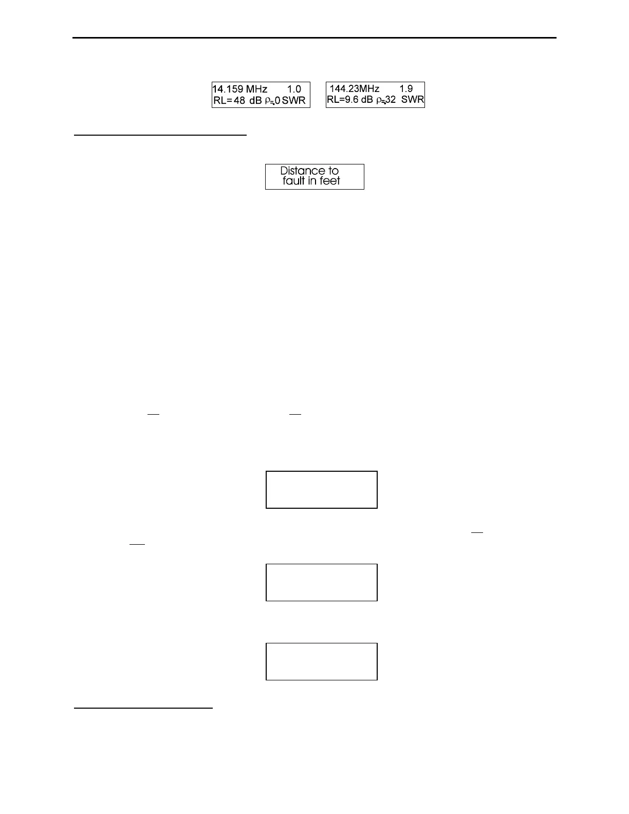
5.5 Distance to Fault mode
From Advance Mode, enter Distance to Fault by tapping Mode twice. The identification screen is shown below:
This mode is useful for finding the physical or electrical length of a random piece of cable, or for finding the distance
to a transmission line fault. Unbalanced lines need not be isolated during testing and may be coiled on the floor. For
balanced lines (ladder line, open-wire feeders, etc), run the MFJ-259D on internal batteries and keep it at least a few
feet away from earth and other conductors. Attach only the DUT (no other wires) -- one lead to the center pin of the
Antenna connector and the other to the case via the grounding stud. Suspend two-wire balanced feeder in a straight
line so it remains clear of metallic objects and ground by at least a few feet.
The Distance to Fault test measures the electrical distance to the transmission line's abnormality. To obtain the
physical distance, multiply electrical distance times the feed line’s specified Velocity Factor (Vf). For example, if
the analyzer display reads DTF = 75 feet and the transmission line is typical RG-8 with a specified velocity factor of
0.66, the physical distance to the fault will be: 75 x .66 = 49.5 feet.
An open or a short-circuit at the fault yields best accuracy -- some resistive and reactive loads or L/C terminations
may skew the results or simply not work. To conduct the test, follow the specific sequence of steps outlined below.
To measure fault distance:
1.) Connect the DUT to the analyzer's Antenna connector. From Advanced mode, tap the Mode switch twice to bring
up the Distance to Fault ID screen. The top line of the working screen will display the VFO frequency in MHz
followed by 1st blinking at a rapid rate. The 1st indicates the analyzer is waiting for entry of the first X=0
frequency. The lower line displays DTF (no data showing) and X with the Reactance reading in ohms.
2.) Begin by searching for the lowest VFO frequency where the Impedance meter shows a sharp null and where the
reactance value on the screen approaches zero (X=0). If possible, find an exact frequency where X=0:
3.) When you've found the first X=0 null, tap the Gate button once to enter it. The blinking 1st will change to a
blinking 2nd. Now, tune to the next higher X=0 null. A minimum reading of a few ohms is acceptable if the X
display won't zero.
4.) Press Gate again, and the display will indicate the DTF. Multiply the DTF times the velocity factor of the cable
(Vf) to get the physical DTF (distance in feet).
5.6 Resonance Mode
From the Advanced menu, tap the Mode switch three times to bring up the Resonance Mode ID screen. The top line
of the working screen displays the VFO frequency in MHz followed by SWR. The lower line displays Resistance (R)
42.648 MHz 2nd
DTF X=1
21.324 MHz 1st
DTF X=0
Dist. to fault
11.3 ft x Vf