MFJ-259D Instruction Manual HF/VHF SWR Analyzer
12
Technical Resources:
As suggested previously, if you wish to delve in and acquire a deeper understanding of electromagnetics and
transmission line theory or the associated vocabulary, it's always best to choose sources that have been peer-reviewed
and edited by professional RF-design engineers. Not all of the casually posted information you'll read online or hear
over the airwaves meets high standards of technical reliability!
5.2 General Connection Guidelines
As before, use the Antenna connector for all RF-measurement except those in Frequency Counter mode. During
testing, the analyzer's VFO (or "stimulus generator") delivers about +7 dBm of RF output (around 0.5 V-RMS), and
appears like a 50 ohm source resistance. The unterminated (open circuit) voltage increases to approximately 1 volt
RMS. Harmonics are better than -25 dBc over the VFO operating range. While the VFO is not frequency stabilized,
it is useful as a discrete signal source for many applications. Also, note that the Antenna connector is not dc-isolated
from the load, so any external bias voltage will couple directly to the internal detectors diodes and potentially
damage them.
IMPORTANT WARNING: Never apply external voltages or RF signals to the antenna connector. Protect this
port from ESD.
Again, use secure RF connections, and keep leads short as possible when measuring components or systems other
than Zo=50 ohms. Also, assume that installing a random-length transmission line between the DUT and the
analyzer's calibration plane can and usually will substantially alter Impedance measurements. When measuring
SWR, use properly constructed 50-ohm coaxial cables of known quality and check connector condition.
5.3 (Magnitude of) Impedance mode
Impedance Magnitude is the first measurement mode in the advanced menu. The MFJ-259D also allows you to view
Impedance Magnitude from the basic-menu SWR/Impedance R&X mode by simply pressing the Gate key. In
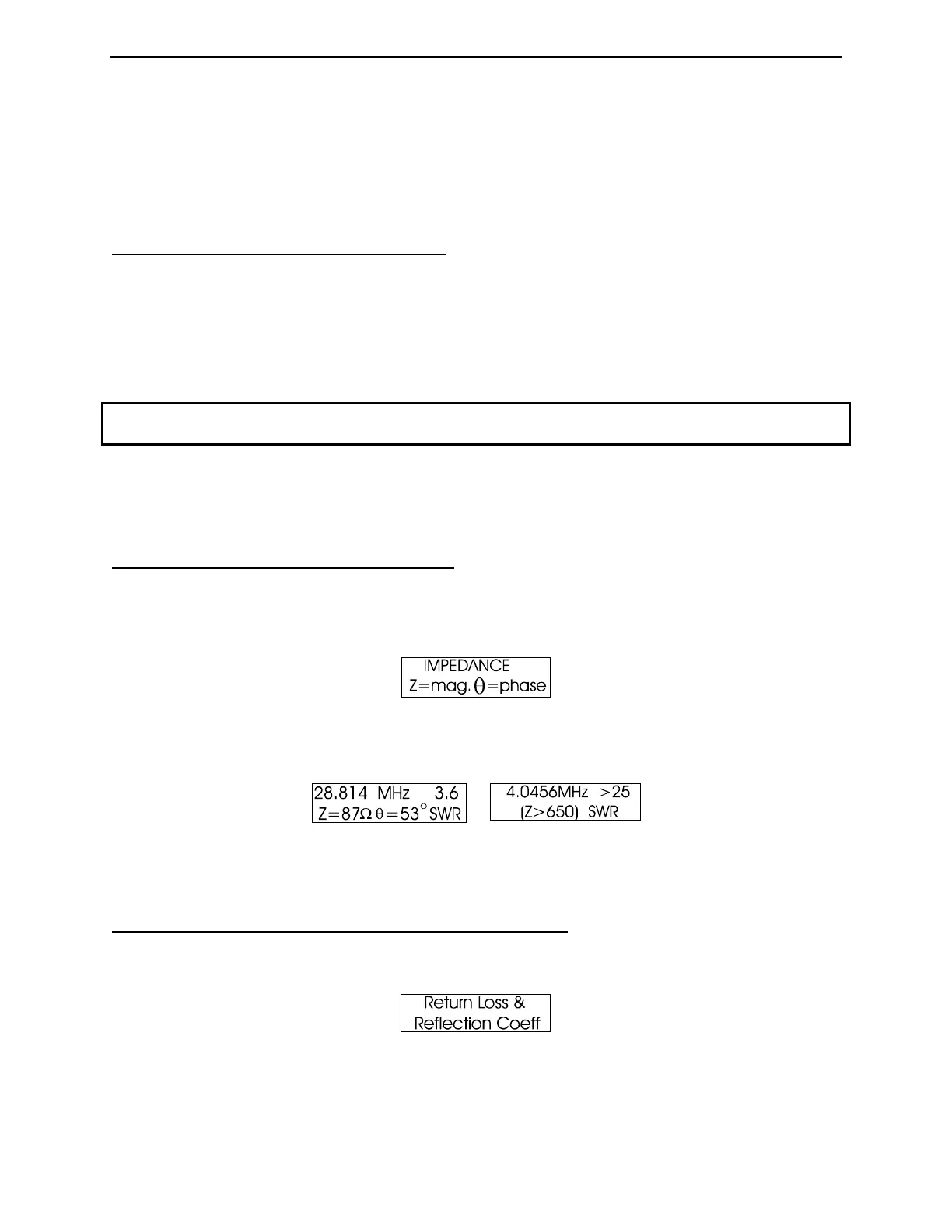
Advanced Mode, the identification screen for Impedance Magnitude is shown below:
The working display presents the VFO frequency, Impedance Magnitude in ohms, and the Phase Angle ( θ ) in
degrees. The analog meters also indicate SWR and Impedance. The maximum impedance limit for this mode is set at
650 ohms, as indicated by the (Z<650) message:
Stray Connector Capacitance: The 4.4-pF stray capacitance contributed by the analyzer's SO-259 connector will
not affect HF measurements and produce only minor errors for Impedances readings at VHF. Error will be most
pronounced at 230 MHz.
5.4 Return Loss and Reflection Coefficient mode
From Advance Mode, open the Return Loss and Reflection Coefficient display by tapping Mode one time. The
identification screen is shown below:
On the working screen, the VFO frequency and SWR are displayed on the top line, while the bottom line presents the
equivalent Return Loss (in dB) and the Voltage Reflection Coefficient (ρ). The analog meters display SWR and
impedance.