MFJ-259D Instruction Manual HF/VHF SWR Analyzer
6
installed, the measured loss will be significantly higher than the actual loss. Note that this measurement mode
only works for lines or devices carrying differential currents.
3.) Capacitance in pF: Use this mode for checking unknown capacitor values (in pF) and for determining how much
reactance a component exhibits at a particular frequency (Xc in ohms). In Capacitance Mode, the top line of the
working display shows the VFO Frequency in MHz and the measured Capacitive Reactance (Xc) at the VFO
frequency (in ohms). The lower line shows the measured capacitance (C) in picofarads (pF). The analog
Impedance meter also displays Xc reactance in ohms.
4.) Inductance in uH: In Inductance Mode, the top line of the working display shows the VFO Frequency in MHz
and the capacitive reactance (XL) at the VFO frequency (in ohms). The lower line shows the measured
inductance (L) in microhenries (µH). The Impedance meter displays reactance in ohms.
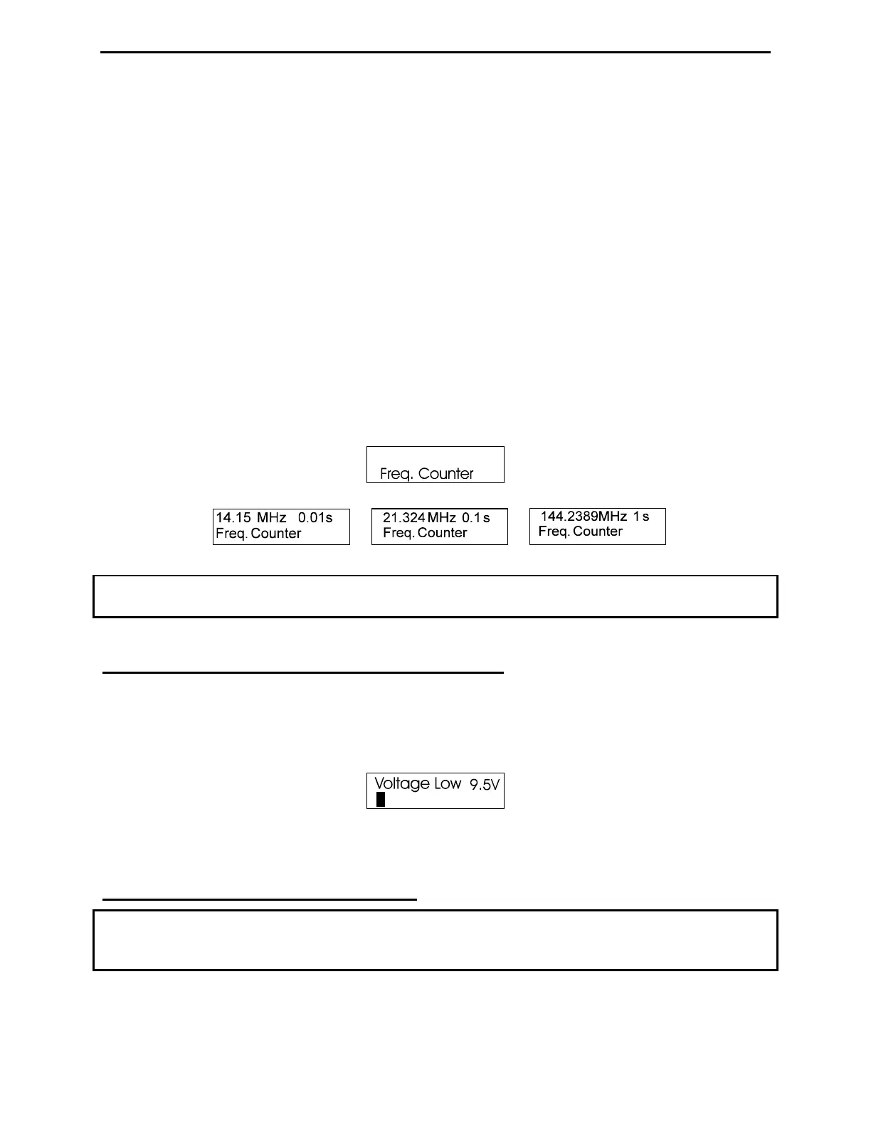
5.) Frequency Counter: The fifth mode converts the analyzer into a discrete frequency counter. Connect the RF
source (DUT) to the BNC connector labeled Frequency Counter Input. As with many counters, the sensitivity
threshold for a locked-in reading gradually decreases with increasing frequency. The measurement threshold at
0.53 MHz is around 10 millivolts -- and this level gradually increases to around 200 millivolts at 230 MHz. The
"never exceed" limit for safe testing is 2-volts peak-to-peak. The counter's default gate time is 0.1 second, but
you may reset it to either .01 second (very fast) or 1.0 second (very slow) by tapping the Gate button. A 1.0-
second gate times provide increased frequency resolution (more digits to the right of the decimal point), and the
.01 gate provides very fast response with less resolution (see sample screens below):
IMPORTANT WARNING: Never apply more than two volts of peak voltage -- or any dc voltage -- to
the Frequency Counter BNC port.
3.4 Blinking “VOLTAGE LOW” display warning
If the external dc source or battery voltage drops below 11 volts, a blinking Voltage Low warning will come up on
the display. Pressing Mode during a low-voltage warning will disable it and allow you to continue testing.
Caution: Measurements made with supply voltages below 11 volts may not be as reliable.
4.0 MAIN (OR OPENING) MODE
IMPORTANT WARNING: Never apply RF or any other external voltages to the Antenna port of this
unit. This unit uses zero bias detector diodes that are easily damaged by external voltages over a few
volts. Also, confirm the power supply is correct, as described in Section-2.0, before operating this unit.
A basic understanding of antenna theory and transmission line behavior will be helpful for making the best use of the
data provided by your MFJ-259D. The ARRL Handbook and ARRL Antenna Book provide concise peer-reviewed