MFJ-259D Instruction Manual HF/VHF SWR Analyzer
16
Antenna connector center pin. The DUT must be suspended and kept away from metallic objects and ground. When
tuning frequency-critical stubs, trim them gradually using the method outlined below:
1.) Determine the DUT's target frequency and calculate the length to formula.
2.) Cut the DUT 20% longer than your calculated length.
3.) At the far end, install a short for 1/2λ and even multiples -- or leave it open for 1/4λ and odd multiples.
4.) Tune VFO to find the frequency of the lowest Impedance null. To fine-tune the null, watch the Reactance (X)
digital display and adjust as close to zero as possible. If your calculations were correct and the feedline Vf
accurate, the null frequency should be about 20% below your target frequency -- reflecting the 20% in added
length.
Continuing:
5.) Divide the present frequency by the desired frequency to calculate a Scaling Factor.
6.) Multiply the Scaling Factor by the feed line’s present physical length to find the desired physical length.
7.) Cut the stub and confirm that the reactance null (X=0) is on the desired frequency.
7.2 Velocity Factor of Transmission Lines
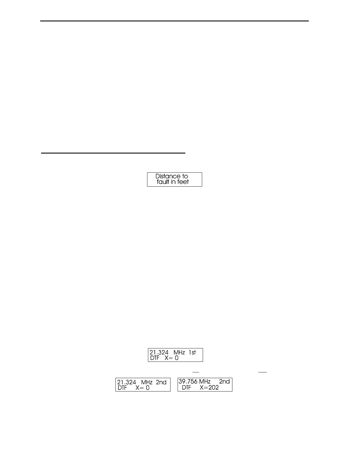
To determine the Velocity Factor (Vf) of a transmission line, select the Distance to Fault mode by entering the
Advanced menu and pressing Mode twice. The opening screen is shown below:
Coaxial lines may be piled or coiled on the floor and the analyzer can be operated on external power. Coax lines are
connect to the analyzer's SO-239 connector with the shield grounded. For balanced line, run the analyzer on its
internal batteries, keep it a few feet away from other conductors and earth, and do not attach any stray wires (other
than the feedline). Connect the DUT with one lead to the analyzer's ground stud and the other to the Antenna center
pin. The DUT must be suspended and kept away from metallic objects and ground.
Note that the far end of the line may be terminated with an open circuit or a short circuit, but should not be
terminated by any other impedance or resistance value.
To compute Velocity Factor, you must measure both the electrical length (DTF) and the physical length of the line.
Velocity factor is calculated by dividing the physical length by the electrical length. For example, if the analyzer
displays an electrical length of 75 feet and the physical length measures 49.5 feet, the velocity factor will be: Vf =
49.5 / 75 = 0.66.
To check reliability, make two or more groups of measurements using different starting frequencies spaced at least
one octave apart. If measured distances agree, your result is confirmed. The more frequencies you use for
confirmation, the greater your assurance that the results are correct.
To measure velocity factor:
1.) Connect the DUT and tune the analyzer VFO to a frequency where the analog Impedance meter nulls and where
reactance displayed on the screen approaches or crosses zero (X=0).
2.) Tap Gate once to enter your first X=0 frequency. The blinking 1st will change to a blinking 2nd.
3.) Tune the analyzer higher (or lower) in frequency until the Impedance meter reads the next null and the display
again crosses zero. If you can't obtain X=0, then a minimum of a few ohms is acceptable.