MFJ-259C Instruction Manual HF/VHF SWR Analyzer
11
5.0 ADVANCED OPERATION
To access the Advanced Mode, press and hold the Gate and Mode buttons simultaneously for several seconds.
When you release, the Advanced message appears on-screen. The Advanced Menu features the following modes:
Impedance.................................................. SWR, impedance magnitude, phase angle of impedance
Return Loss and Reflection Coefficient...... SWR, return loss, impedance, reflection coefficient
Distance to fault.......................................... SWR, impedance, and distance to fault
Resonance ................................................. SWR, resistance and reactance
Transmit efficiency ..................................... SWR, Impedance, Forward power as percentage of apparent power
5.1 Forward
In Advanced Mode, the MFJ-259D measures:
(1.) Distance to Fault,
(2.) Impedance Magnitude,
(3.) Reactance,
(4.) Resistance,
(5.) Standing Wave Ratio (SWR).
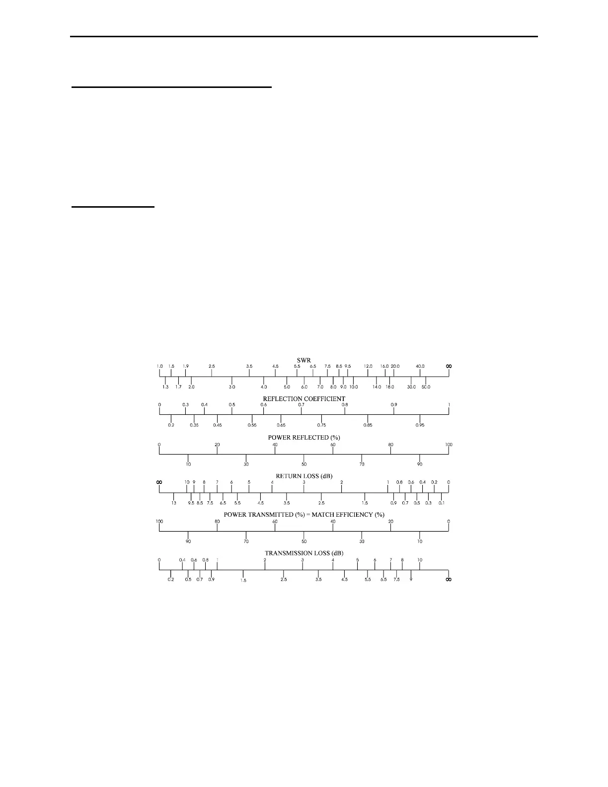
It also converts basic SWR data into alternative parameters such as Return Loss, Reflection Coefficient, Match
Efficiency, Transmission Loss, and Percentage of Apparent Power in the system (see equivalency chart below). All
of these terms have a corresponding SWR value attached to them, so if they seem unfamiliar and you have no
specific need to apply them, sticking with basic SWR measurements will serve you just as well!
MFJ-259D Limitations for Advanced Measurements:
The analyzer's coupler uses a 50-ohm bridge with voltage detectors across each leg. An eight-bit microcontroller
processes these voltages and applies formulas to derive useful information from them. The basic calculations are
Resistance, Reactance, SWR, and Complex Impedance. In accuracy challenged modes, the system crosschecks itself
and presents a weighted average of the most reliable information. The overall resolution of the system is limited by
eight-bit A/D conversion while some of the formulas contain square-law and higher-order functions. As a result,
some data jumping may occur at the edges of a least-significant-bit. The resolution of the analyzer's compensated
detector is accurate to about 0.5 %, and to minimize the opportunity for error, we use the most direct calculations
possible.