MFJ-259C Instruction Manual HF/VHF SWR Analyzer
19
7.6 Testing RF Transformers
The MFJ-259D can test any RF transformer presenting a 25-100 ohm termination on one of its windings. Connect
the 25-100 ohm winding to the analyzer's Antenna jack using a very short 50-ohm pigtail (<1° phase shift). The other
winding (or windings) should be terminated with a low-inductance resistor equal to the desired load impedance.
Sweep the analyzer's VFO across the DUT's intended operating range. Use the basic SWR, Resistance (R) Reactance
(X) Mode (plus the Impedance Magnitude [Z] option) to evaluate the DUT's impedance and useable bandwidth. You
may also measure the transformer's efficiency by comparing the source voltage generated by the MFJ-259D to the
load voltage using standard power-level conversions.
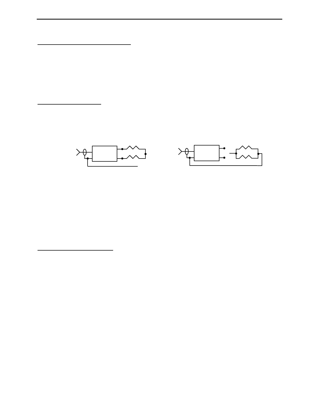
7.7 Testing Baluns
To test balun performance, connect the analyzer Antenna jack to the balun's 50-ohm unbalanced input. Terminate the
balanced side with two equal-value load resistors connected in series to make up the required load impedance. For
example, to test a 200-ohm (4:1) secondary, use a pair of 100-ohm carbon (non-inductive) resistors in series, as
shown below in Fig A:
Balun
>
A
C
B
Clip Lead
50 Ohms
Unbal
R1
R2
Balun
Clip Lead
50 Ohms
Unbal
R1
R2
<
A
C
Fig A
Fig B
A properly designed current balun works best for maintaining current balance. It also has the highest power
capability and lowest loss for given materials. To evaluate the balun (DUT), measure SWR while connecting the
grounded clip lead to point A, B, and C. When functioning properly, a current balun will exhibit low SWR over its
entire operating range with the clip lead installed at any of those three positions.
A well designed voltage balun should show low SWR over its operating range with the clip lead installed at position
B, but show poor SWR with the clip lead is installed at A or C (note, however, that the SWR readings should
measure about the same whether connected to A or C). A voltage balun should also be tested using the configuration
shown in Fig B, with the resistors in parallel. If it is operating properly, SWR will be remain low with the resistors
connected from either output terminal to ground.
7.8 Testing RF Chokes
For testing self-resonance in chokes, use the analyzer in basic SWR, Resistance (R) + Reactance (X) Mode. Large RF
chokes often have frequencies where distributed capacitance and inductance form a low impedance series-resonance.
Series resonance occurs because the choke winding acts like a succession of back-to-back L networks. This
condition can potentially result in three problems:
1.) The end-to-end Impedance of the choke becomes very low.
2.) The voltage at the center of the resonant point becomes very high, often causing severe arcing.
3.) The current in the winding becomes very high, often resulting in severe heating.
To detect troublesome series resonance, install the choke in its designated operating location and connect the
analyzer in an end-to-end configuration through a short 50-ohm jumper cable (with no other connections). Slowly
sweep the choke's operating range looking for impedance dips that identify low-impedance series-resonant
frequencies. When detected, move a small insulated screwdriver blade along the choke to find a point where the
series-resonate impedance changes suddenly. This is the region that has the highest voltage present, and the area
where adding or subtracting even a tiny amount of capacitance had the greatest effect. To shift the resonance out of
the desired frequency range, try removing turns to reduce capacitance -- or adding a capacitive stub. A small change
in capacitance has a much more impact than making a small change in inductance because the ratio of L to C is so
high.