MFJ-269C Instruction Manual LF/HF/VHF/UHF SWR Analyzer
20
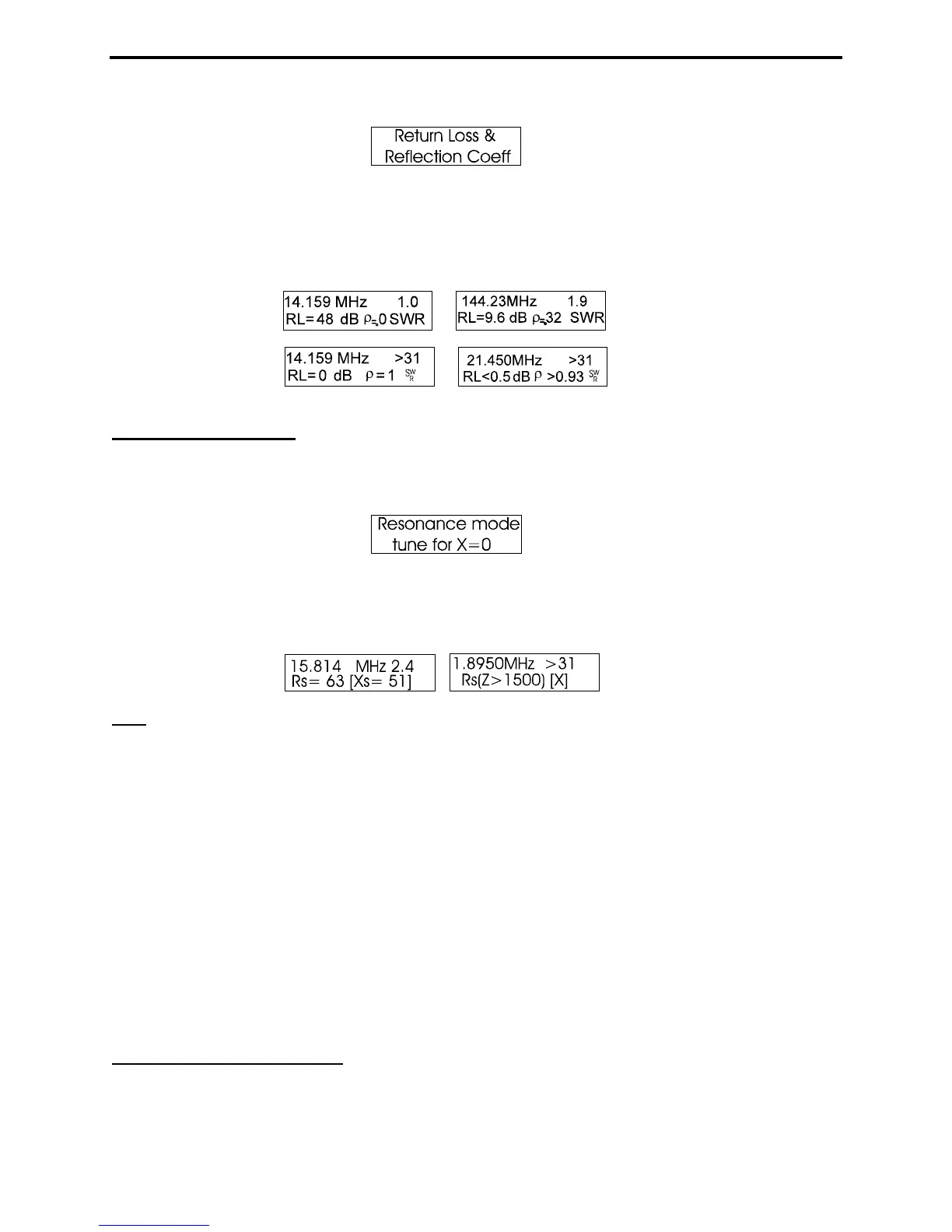
The Return Loss and Reflection Coeff mode measures and displays Return Loss in dB along with the
Voltage Reflection Coefficient. These measurements are alternative terms that describe SWR. In this
mode, the analog meters indicate SWR (normalized to 50 Ohms) and Impedance (Z). To use this mode,
connect the DUT to Antenna and adjust the VFO for Frequency. Sample display screens are shown
below:
5.4.1.5 Resonance
To access Resonance Mode, enter Advanced-1 and then press Mode twice. If already in Advanced-1,
scroll to it using the Mode switch. The entry screen is shown below:
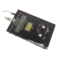
Resonance Mode draws attention to reactance, displaying it on the Impedance meter as an analog tuning
aid for identifying resonance. In this mode, the MFJ-269C measures and displays Frequency, SWR,
Resistance (Rs), and Reactance (Xs). When reactance equals zero in a system that has selectivity, the
system is said to be resonant.
Note
: Because of transmission line effects, zero-reactance (or resonance) can occur on frequencies where
the antenna is not actually resonant. Conversely, an antenna may appear to contain reactance even at its
true resonant frequency when it is measured through a feedline. A less-than-perfectly matched antenna
and feedline, when used with a feedline that is not an exact multiple of 1/4 wavelength (0, 1/4, 1/2, 3/4,
etc.), will have reactance added by the feedline. Reactance added by a non-quarter wave multiple
mismatched feedline may coincidentally cancel a non-resonant antenna’s reactance, making the system
resonant.
The SWR of the system, if the feedline is a true 50-ohm feedline (or any impedance feedline that matches
the normalized (Zo) impedance setting of the instrument) with minimal loss and free from common mode
currents, will not change as the feedline length is changed. This is true even if the resonant frequency or
reactance changes.
Resonance Mode functions like other SWR and impedance modes, with the exception the Impedance
meter measures only reactance. This allows the operator to easily locate frequencies where system
reactance crosses zero.
5.4.1.6 Match Efficiency