ELECTRICAL
1
.oJ
CAL
with the local regulations. To adjust, remove the lamp rim and set each lamp
to the correct position in the vertical plane by turning the adjusting screw at the
top of the light unit
ina
clockwise direction to raise and anti-clockwise to
lower the beam. Horizontal adjustment is made by turning the adjustment screw
on each side of the light unit. On the sealed-beam type of light unit there is
only one horizontal adjustment screw.
Remember
that
the setting of the beams is affected by the load on the car
and the consequent spring deflection. The lamps should therefore always be
set with the normal load on the car.
Avoid setting the main beams above horizontal; they will dazzle oncoming
traffic
and
give inferior
road
illumination.
Checking and resetting should be carried out
at
the beginning of each winter.
This work is best entrusted to a -Distributor/Dealer, who will have specialist
equipment available for this purpose.
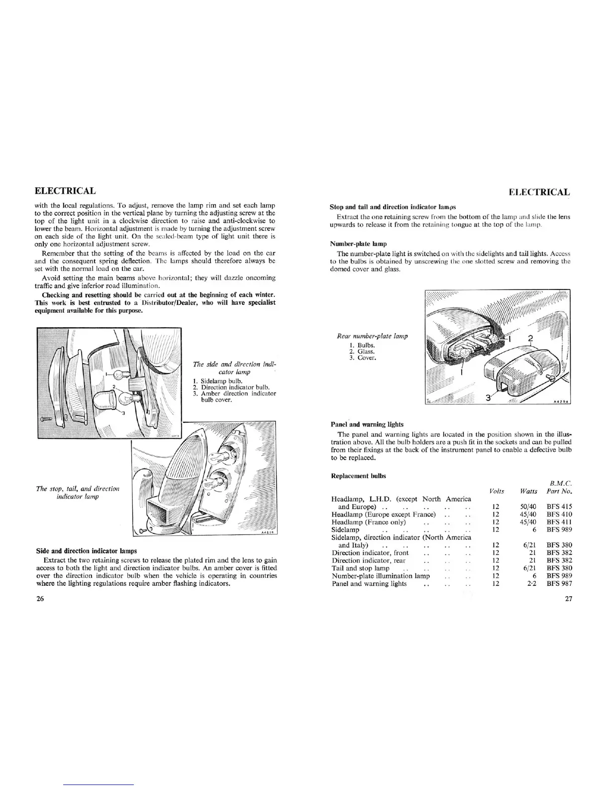
The side and direction indi-
cator lamp
1. Sidelamp bulb.
2. Direction indicator bulb.
3. Amber direction indicator
bulb cover.
The slop, tail, and direction
indicator lamp
Side and direction indicator lamps
Extract the two retaining screws to release the plated rim and the lens to gain
access to
both
the light
and
direction indicator bulbs. An amber cover is fitted
over the direction indicator
bulb when the
vehicle
IS
operating in countries
where the lighting regulations require amber flashing indicators.
26
Stop and tail and direction indicator lamps
Extract the one retaining screw from the bottom of the lamp and slide the
I ns
upwards to release it from the retaini ng tongue at the top of the lamp.
Number-plate lamp
The number-plate light is switched on with the sidelights
and
taillights. Access
to the bulbs is obtained by unscrewing the one slotted screw and removing the
domed cover and glass.
Rear number-plate lamp
1. Bulbs.
2. Glass.
3. Cover.
Panel and warning lights
The panel
and
warning lights are located in the position shown in the illus-
tration above. All the bulb holders are a push fit in the sockets and can be pulled
from their fixings at the back of the instrument panel to enable a defective bulb
to be replaced.
Replacement bulbs
R.M
.C.
Volts
Watts
Part No.
Headlamp, L
.R
.D.
(except
North
America
and
Europe)
..
12
50/40
BFS 415
Headlamp (Europe except France)
12
45/40
BFS 410
Headlamp (France only)
12
45/40
BFS 411
Sidelamp
12
6
BFS 989
Sidelamp, direction indicator (North America
and Italy) 12
6/21
BFS 380
Direction indicator, front
12 21
BFS 382
Direction indicator, rear
12
21
BFS 382
Tail and stop lamp 12
6/21
BFS 380
Number-plate Hiumination lamp
Ii
6 BFS
989
Panel and warning lights 12
2·2 BFS 987
27