C
ONT
ROLS AND INSTRUMENTS
Ignition warning light
The
ignition
war
ning light serves
the
dual
pu
rpose
of
reminding
the
driver to
switch
off
the
ignition,
and
of
acting
as a
no-ch
arge indicator.
With
the
igni
tion
switched
on
the
warning
li
ght
should
onl
y be
illuminated
when
the
engine is
not
ru
nning, or is
running
at
a very low speed. As
the
engine speed increases
the
light
should
dim an d
then
go o
ut
at
a fairly
low
engine speed.
If
the
li
ght
fails
to
go
out
until higher engine speeds
are
reached
or
remains
alight
at all times,
inspect
the
dynam
o dri ving
belt
for
correct
tension
or
breakage
.
If
the
belt
is in
order
the
chargin
g system mus t be
overhauled
by a
Distributor
or
Dealer.
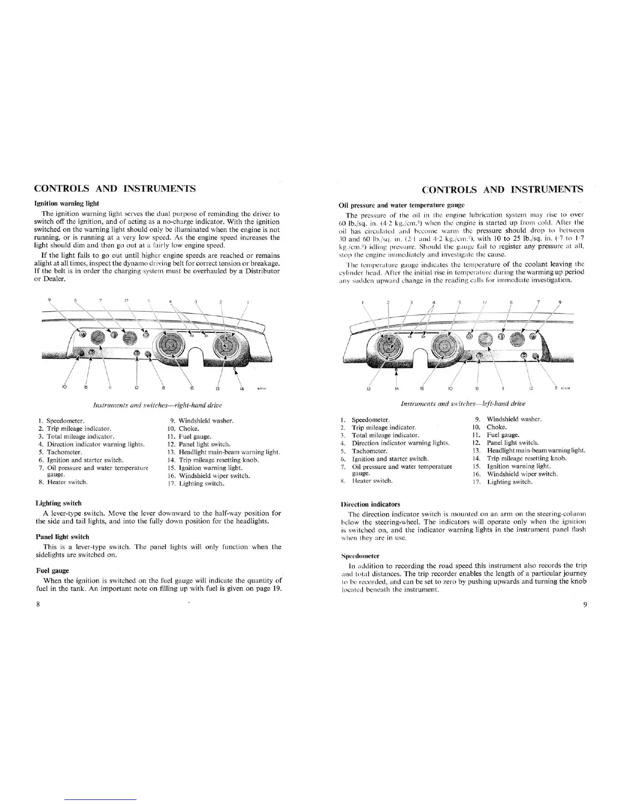
Instruments and switch
es-
right-hand drive
CONTROLS AND INSTRUMENTS
Oil pressure
and
water temp
eratu
re gauge
The
pressure
of
the oil in the
eng
ine
lubrication
system may rise to ove r
60
lb. jsq . in. (4,2 k -Y./cnl .
2
)
wh n the engine is s
tarted
up
from
cold . After the
oil has circulated
and
become
warm
the press
ure
sh
ould
drop to between
30
and
60 lb.rsq . in. (2·1 and 4·2 kg.jcm."), with 10 to 25 lb.jsq, in.
('7
to 1·7
kg.rcrn.")
idling prcssur . l- h
ould
the gau ge fail to register
any
pressure
at
all,
s
top
the engine imrn diatcly and investigate the cause.
The temp .ruturc gauge indicates the
temp
erat
ure
of
the
coolant
leaving the
cylinder hcad . After the initial rise in tem perat ure
durin
g
the
warmi
ng up
period
any sudden
upward
change in the re
adin
g ca lls for imm
ediate
investigation.
Instruments and switches
-left-hand
drive
1. Speedometer.
2. Trip mileage indicator.
3.
Total
mileage indicator.
4.
Dire
ction indicator warning lights.
5. Tachometer.
6. Ignition
and
starter switch .
7. Oil pressure and water temperature
gauge.
8.
Heater
switch.
9. Windshield washer.
10.
Choke
.
11.
Fuel
gauge.
12. Panel light switch.
13.
Headl
ightma
in-beam warning light.
14. Trip mileage resetting
knob
.
15. Ignition warning light .
16. Windshield wiper switch.
17. Lighting switch.
1. Speedometer.
2.
Trip
mileage indicator.
3.
Total
mileage indicator.
4. Direction indicator warning lights.
5. Tachometer.
6.
Jgnition
and
starter switch.
7. Oil pressure
and
water temperature
gauge.
~
.
I-{eaterswitch.
9. Windshield washer.
10. Choke.
11.
Fuel
gauge.
12. Panel light switch.
13. Headlightmain-beamwarninglight.
14. Trip mileage resetting
knob
.
15. Ignition warning light.
16. Windshield wiper switch.
17. Lighting switch.
Lighting switch
A lever-type switch.
Move
the
lever
downward
-to
the
half-way
position
for
the
side
and
taillights
,
and
into
the
fully
down
position
for
the
headlights.
Panel
light switch
This
is a lever-type switch.
The
panel
lights will
only
function
when
the
sidelights
are
switched
on.
Fue
l gauge
When
the
ignition
is switched
on
the
fuel
gauge
will indicate
the
quantity
of
fuel in
the
ta~k.
An
important
note
on
filling
up
with
fuel is given
on
page
19.
8
Direction indicators
The
dir
ecti
on
indicator
swi
tch
is
mounted
on
an
arm
on
the steering-column
I "I w
the
ste
erin
g-wheel. The in
dicators
will
operate
only
when
the
ignition
i.. switched
on
,
and
the
indicat
or
warning
lights in
the
instrument
panel
flash
h .n they are in use.
..'I) -edou -ter
It ad di
ion
to rec
ording
the
road
speed
thi
s
instrument
also records
the
trip
an I
tota
l di tances.
Th
e
trip
recorder
enables
the
length
of
a
particular
journey
~
~
)
h:
!"
:
<;QrQ~
Q;
~!1Q
~~!!
be set t9
?;~r9l>y
pushing
upwards
and
turning
the
knob
locut xl b neath
the
instrument.
9