WIRING DIAGRAM
KEY TO
WIRIN
G DIAGRAM
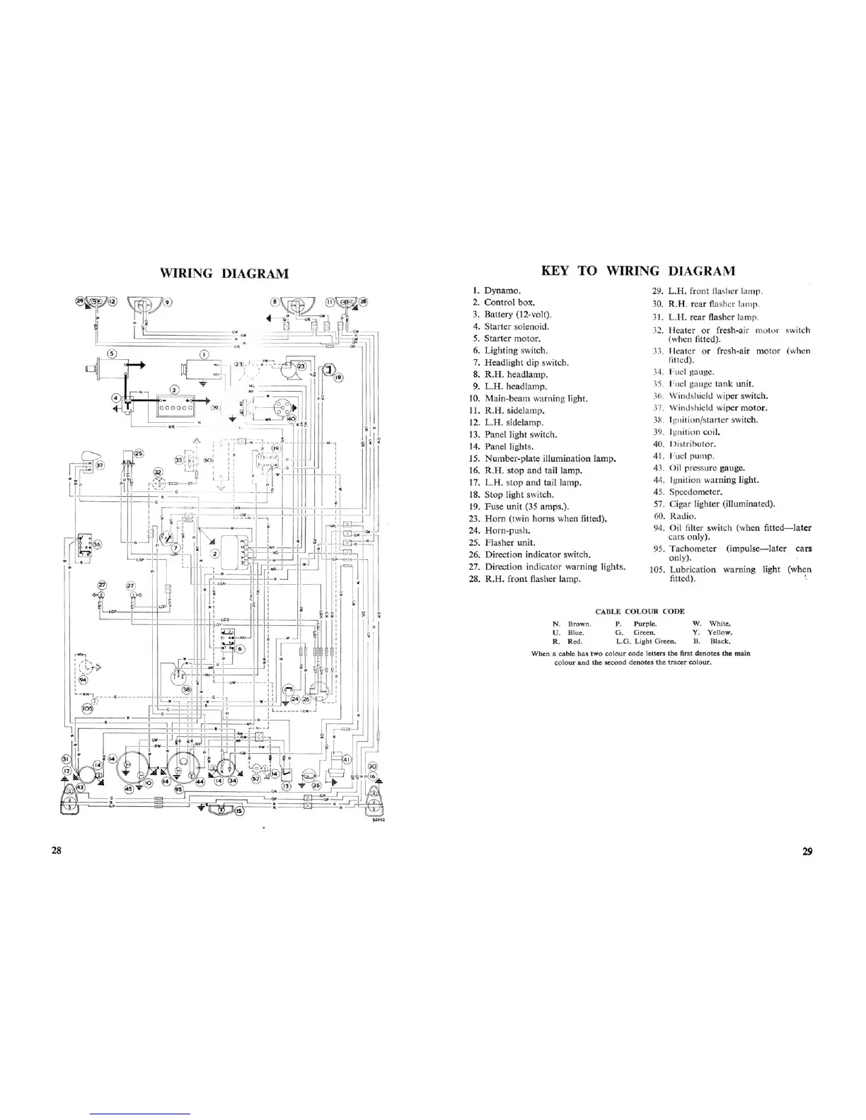
When
a cable has two
colour
code
letters the first
denotes
the main
colour
and
the s
econd
denotes
the
tracer
colour.
CABLE
COLOUR
CODE
P.
Purple.
G.
Green.
L
.G.
Light
Green.
~
I ir
I
&2662
1. Dynamo.
2. Control box.
3. Battery (12-volt).
4. Starter solenoid .
5. Starter motor.
6. Lighting switch.
7. Headlight dip switch.
8. R.H. headlamp.
9.
L.H
. headlamp .
10. Main-beam warning light.
11. R.H. sidelamp.
12. L.H. sidelamp.
13. Panel light switch.
14. Panel lights.
15. Number-plate illumination lamp.
16.
R.H.
stop
and
tail lamp.
17. L.H. stop and tail lamp.
18. Stop light switch.
19. Fuse unit (35 amps.).
23.
Hom
(twin horns when fitted).
24. Horn-push.
25. Flasher unit.
26. Direction indicator switch.
27. Direction indicator warning.lights.
28.
R.H.
front flasher lamp.
N. B
rown
.
U. Blue.
R.
Red
.
29. L.H . front flasher lamp.
30. R.H. rear flasher lamp.
31. L.H. rear flasher lamp .
32. Heater or fresh-air
motor
swit h
(when fitted).
33. Heater or fresh-air moto r (when
fitted).
34.
Fuel gauge.
35. Fuel gauge
tank
unit.
3(). Windshield wiper switch.
37. Windshield wiper motor.
38. Ignition/starter switch.
39. Ignition coil.
40. Distributor.
41.
f uel pump.
43. Oil pressure gauge.
44. Ignition warning light.
45. Speedometer.
57. Cigar lighter (illuminated).
60. Radio.
94. Oil filter switch (when fitted
-la
ter
cars only).
95. Tachometer
(impulse-later
cars
only).
105. Lubrication warning light (when
fitted).
~
.
W. White.
Y. Yellow.
B. Black.
28
29