XTP601 User’s Manual
Michell Instruments v
Figures
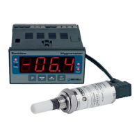
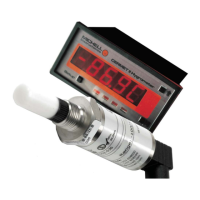
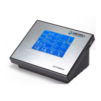
Figure 1 XPT601 Oxygen Analyzer Versions ..............................................................1
Figure 2 Initializing Screen .......................................................................................5
Figure 3 Main Page ..................................................................................................5
Figure 4 User Interface ............................................................................................6
Figure 5 XTP600 Series Application Software .............................................................6
Figure 6 ESC Button ................................................................................................7
Figure 7 Up/Down Arrow Buttons .............................................................................7
Figure 8 ENTER Button ............................................................................................7
Figure 9 Menu Map ..................................................................................................9
Figure 10 Main Page ................................................................................................10
Figure 11 Chart Page ...............................................................................................11
Figure 12 Secondary Parameters Page ......................................................................12
Figure 13 O2 Min/Max Page .....................................................................................12
Figure 14 Alarms Log Page ......................................................................................13
Figure 15 Info Page .................................................................................................13
Figure 16 User Set-Up Variables Page .......................................................................14
Figure 17 Settings Page ...........................................................................................15
Figure 18 HMI Page .................................................................................................16
Figure 19 Clock Page ...............................................................................................16
Figure 20 Reset Page ...............................................................................................17
Figure 21 Outputs Page ...........................................................................................17
Figure 22 External Compensation Page .....................................................................18
Figure 23 External Sensor Page ................................................................................19
Figure 25 Field Cal Page ..........................................................................................20
Figure 26 1 Point Calibration Page ............................................................................23
Figure 27 2 Point Calibration Page ............................................................................24
Figure 28 Field Calibration Reset Page ......................................................................25
Figure 29 XTP601 Cutaway Showing Major Components ............................................28
Figure 30 XTP601 Lid Removal .................................................................................29
Figure 31 XTP601 Cable Entries ................................................................................30
Figure 32 Terminal Block Locations ...........................................................................31
Figure 33 XTP601 Dimensional Drawings ..................................................................38
4.4 Mechanical Installation ...................................................................................... 30
4.4.1 Gas Connection ........................................................................................... 30
4.4.2 Sample Gas Requirements ........................................................................... 30
4.4.3 Calibration Gases ........................................................................................ 31
4.5 Electrical Installation ......................................................................................... 31
4.5.1 Power Supply and Input/Output Signal ......................................................... 31
4.5.2 Power Supply (PL9 - Green) ........................................................................ 31
4.5.3 Signal Output ............................................................................................. 32
4.5.4 Serial Output .............................................................................................. 32
4.5.5 Analog (4-20 mA) Outputs and Communications (PL5 - Green) ....................... 32
4.5.6 Alarm Relay Contacts (PL1- Black) ................................................................ 33
4.5.7 Analog (4-20 mA) Inputs and Sensor Excitation Voltage (PL4 - Green) ............ 33
4.5.8 Light Guide ................................................................................................. 34