SW800 Installation Manual
34
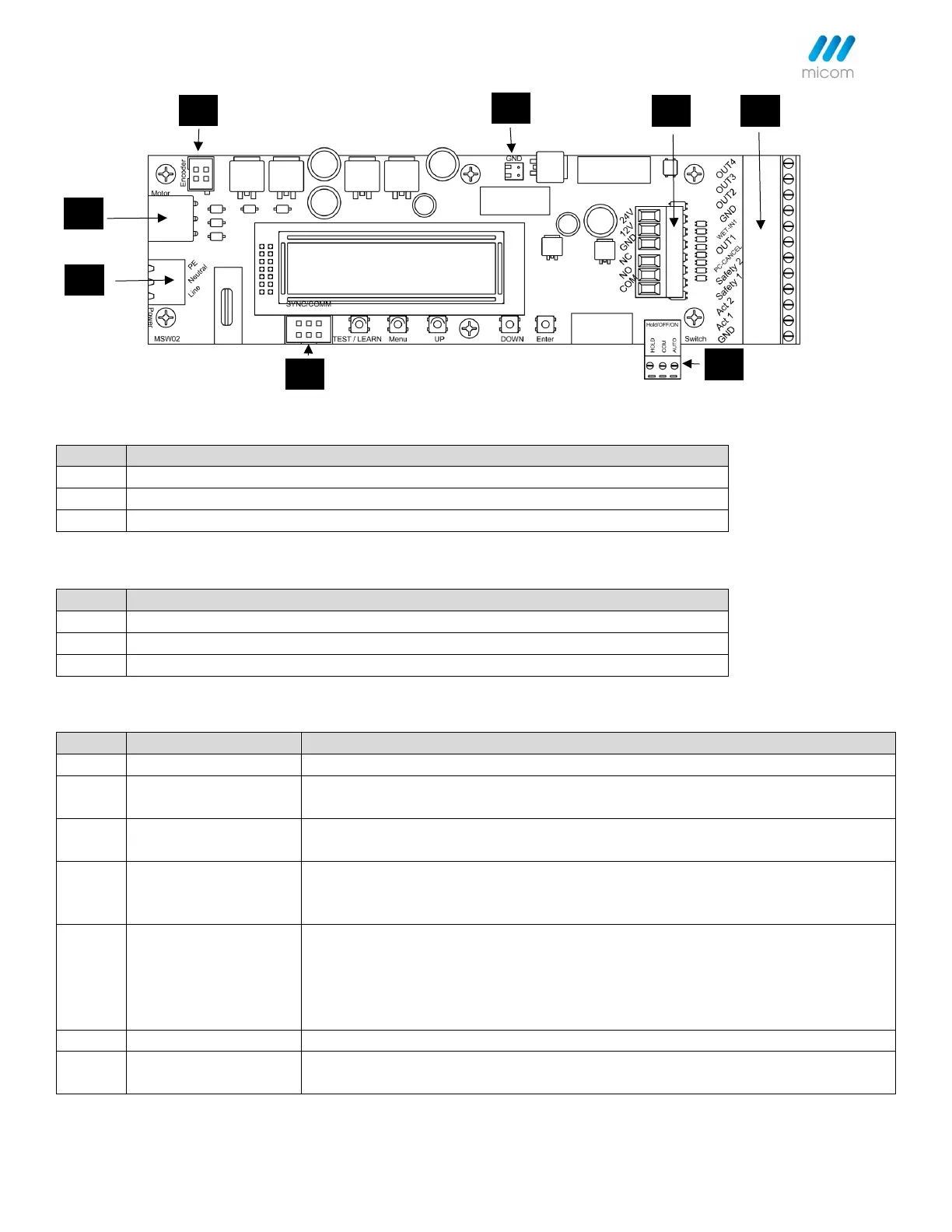
J1 - Connector Description: Power input 100-240VAC (100W max.)
J2 - Connector Description: Hold open/OFF/Auto switch input
Auto signal - This signal (to GND) will allow activation
GND - Ground reference for signal and power
Hold Open - This signal (to GND) will activate the operator to hold the door open.
J3 - Connector Description: Accessories and Sensors Inputs and Outputs
Ground reference for signal and power.
(Input) This signal (to COM) will activate the operator. If "AUTO" signal (J2.3) is to
COM and no current fault is present.
(Input) This signal (to COM) will activate the operator. (If "AUTO" signal (J2.3) is to
COM with no current fault present and door is not fully closed.
(Input) When the door is fully closed, this signal (to COM) will prevent an
activation. When the door is fully opened, this signal (to COM) will prevent the
door from entering the closing cycle.
(Input) When the door is fully closed, this signal (to COM) will prevent and
activation. When safety signal clears, pending activation will activate the operator.
During the opening cycle, the door will go to safety (Hold) speed. (When the signal
is to COM). When the door is fully opened, this signal (to COM) will prevent the
door from entering the closing cycle.
(Input) This signal (to COM) will prevent or cancel power close.
(Output) This signal is tied to COM when door is fully closed. Door must be set up
(Learning Completed).