SW800 Installation Manual
9
Section 5.0 - Operator Installation
The following information gives a complete guidance to the correct installation on the SW800 operator.
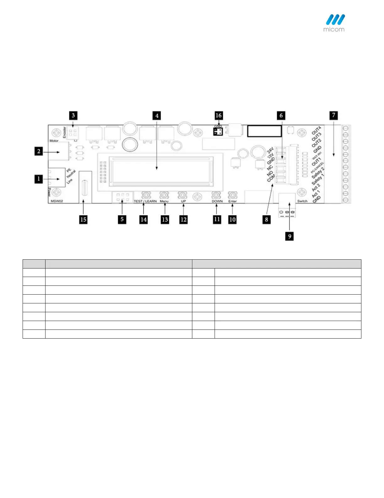
5.1 Control Unit
Power Unit (90-250VAC 50/60hz)
3 Position Switch Input Connector
Motor Encoder Connector Plug in
Sync/Comm Connector Plug in (Double Operator)
24VDC/12VDC Power Output Connector
Activation/Safety Accessories Connector
Battery Back-up Connection
5.2 Operator Handing and Orientation
Verify that the operator is the correct orientation. Left Push, Right Push, Left Pull, or Right Pull.
Note:
• If the operator label is facing 'Down' to the floor, the handing is Left Hand Push/Pull.
• If the operator label is facing 'Up' to the ceiling, the handing is Right Hand Push/Pull.