SW800 Installation Manual
14
Section 6.0 - Push and Pull Arms Installation
Following these simple steps will allow the door to be set up quickly and correctly. Refer to installation drawings below.
6.1 Push Standard Scissors Arm for 0" - 14" Reveals
Note: Base rail to be mounted flush with the bottom of the door frame.
A solid spacer material or filler may be required to compensate for any gap between the back of base rail and wall.
Ensure, before fixing base rail to the door frame, that access holes for power supply cables are in line, if required.
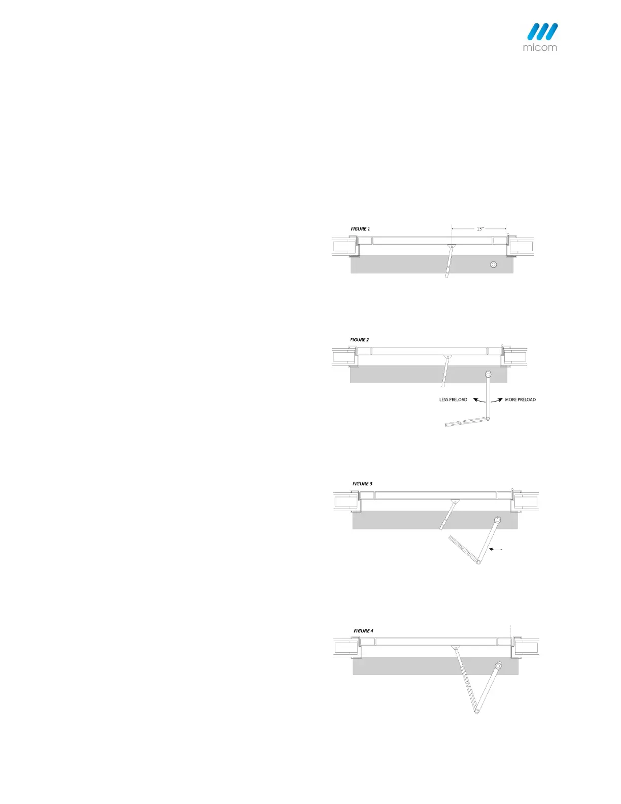
Step 1: With door closed, attach shoe of the arm to
the door panel @ 13” from hinge edge. Fig. 1.
Step 2: Install power section of the arm to the
spindle on the operator @ 85°-90° from the hinge
side. Fig. 2.
Step 3: Rotate the attached arm from the above
85°-90° to about 110° from the hinge side. Fig. 3.
Step 4: Align and connect both the arms of the shoe
and power section. Slide the adjustable track
together and tighten the screws. Fig. 4.
Increase or decrease spring pre-load by rotating the
power section arm while attaching to the spindle.
Fig. 2.
Step 5: Press TEST/LEARN button to begin the
learning cycle. See Learning Door Cycle.