Page 11
Installation and Assembly
IF2030/ENETIP
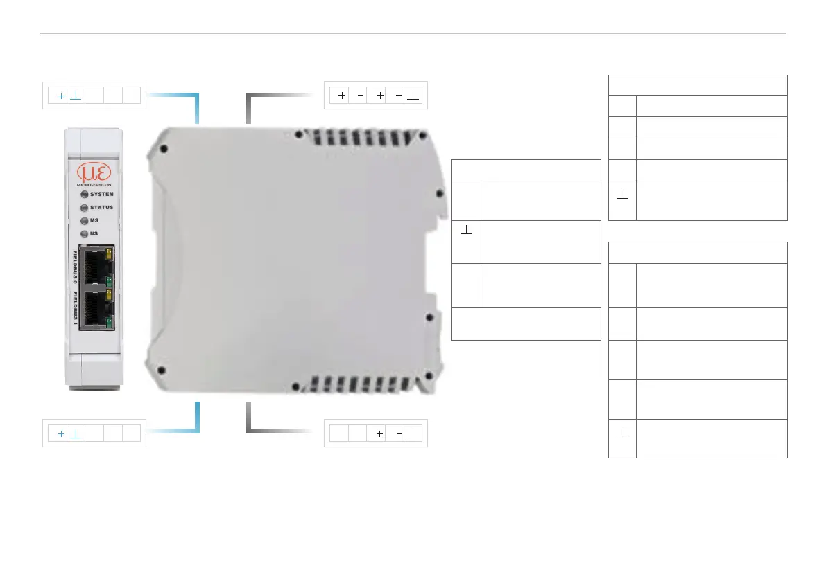
4.2 Pin Assignment
Terminal 1 Terminal 3
Terminal 2 Terminal 4
A B S S
T RRT
M1M2V
M1M2V
Terminal 4
T+ RS422 Tx+
T- RS422 Tx-
R+ RS422 Rx+
Terminal 1 and 2
R- RS422 Rx-
V+ Supply
voltage
2
Ground
1
e.g., for RS422
shield connection
Ground for supply
voltage
Terminal 3
M1,
M2
Multifunction input
1/2 sensor (e.g., for
laser on/off)
A RS485 A
Terminal 1 and 2 connec-
tions daisy-chained
B RS485 B
S+ Synchronization output +
S- Synchronization output -
Ground
1
e.g., for RS485
shield connection
Fig. 2 Interface module terminals
1) Internally connected to supply ground 2) If the distance between IF2030/PNET and the sensor/controller is long, a
separate supply for the sensor/controller may be advisable.
 Loading...