Page 15
Installation and Assembly
IF2030/ENETIP
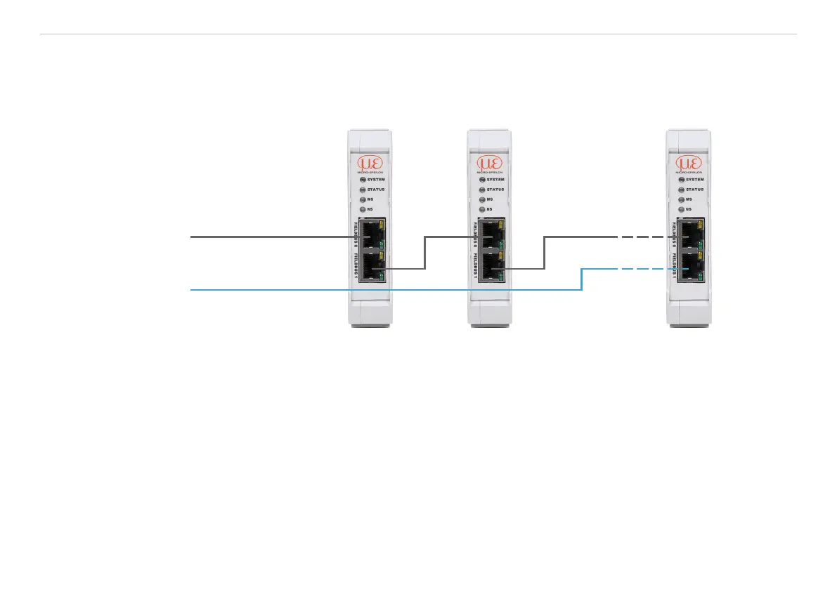
4.3 Fieldbus Cabling
During cabling, channel 0 of the scanner is connected to a port of adapter 1 (slave device).
The second port of the adapter 1 is connected to the port of the next adapter, etc. One port of the last adapter
and channel 1 of the master device (scanner) remain unused.
Scanner
Adapter 1 Adapter 2
Redundancy
Adapter n
Fig. 10 Cabling in the EtherNet/IP network
Optional: IF2030/ENETIP can participate in a device level ring as a ring node and thereby reduce the threat
of failures through redundant cabling.
 Loading...