Page 45
Electrical Installation
thermoIMAGER TIM
6.2 Process Interface
The TIM is equipped with a process interface (cable with integrated electronics and terminal block), which
can be programmed via the software as an Analog Input (AI) and Digital Input (DI) in order to control the cam-
era or as an Analog Output (AO) in order to control the process. The signal level is always 0 - 10 V
(DI = 24 V).
Please make sure that the process interface (electronics within cable as well as industrial interface) is pow-
ered separately (5 - 24 VDC).
> With no external power supply the PIF will not work
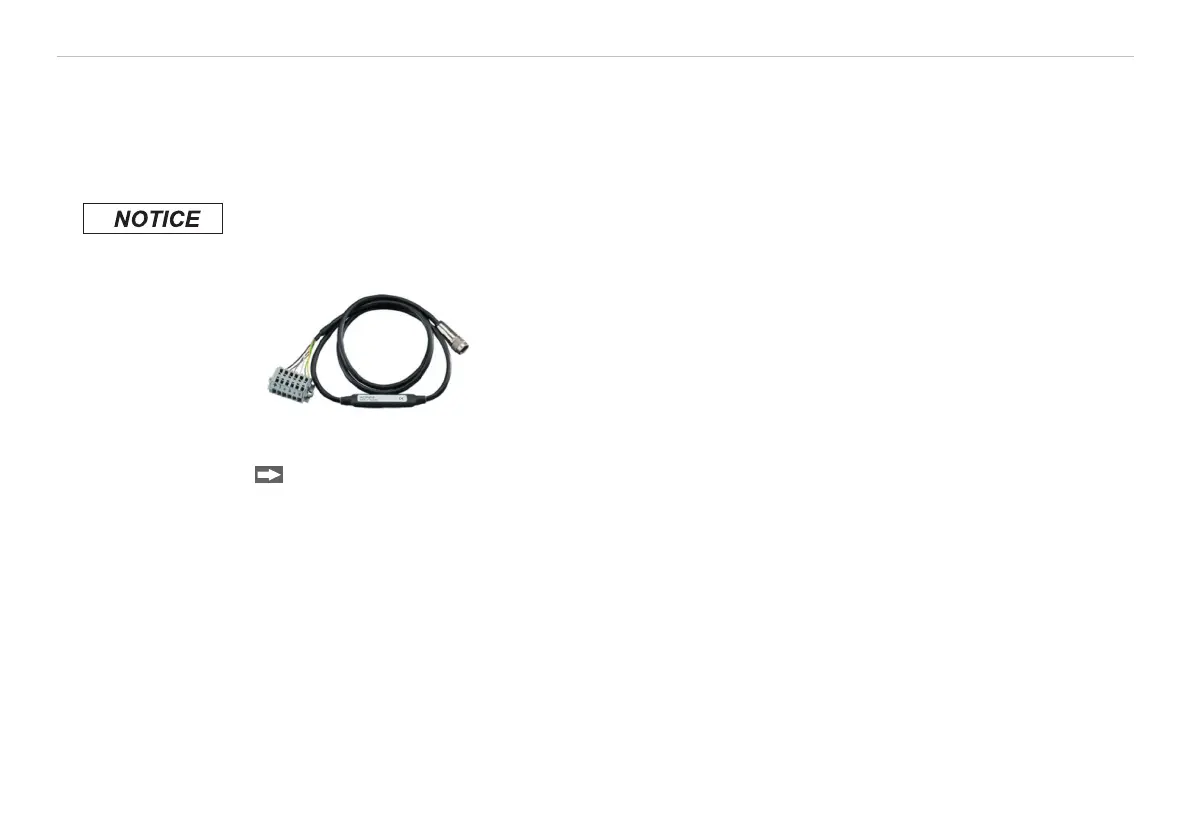
Fig. 19 Prozess interface
Connect the PIF cable to the camera before switching on the power.
The process interface can be activated choosing the following options:
Analog Input (AI): Emissivity, ambient temperature, reference temperature, uncomitted value, flag
control, triggered recording, triggered snapshots, triggered linescanner, triggered event
grabber, reset peak-/value-hold, switch temperature range
Analog Output (AO): Main measure area, measure area, internal temperature, flag status, recording status,
line scan status, alarm, frame sync, fail-safe, external communication
Digital Input (DI): Flag control, triggered snapshots, triggered recording, triggered linescanner, triggered
event grabber, reset peak-/value-hold, switch temperature range
 Loading...