Do you have a question about the MICRO-EPSILON thermoIMAGER TIM Series and is the answer not in the manual?
Explains symbols for warnings, cautions, and user actions in the manual.
Provides critical safety warnings regarding electrical hazards, energy sources, and EMF.
Details CE marking requirements and relevant EU directives for the thermoIMAGER TIM.
Specifies the intended industrial and laboratory applications for the thermoIMAGER TIM.
Defines operating/storage temperature ranges and relative humidity for the device.
Explains how the thermoIMAGER TIM calculates surface temperature using infrared energy.
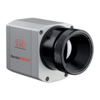
Compares different TIM camera models, their specifications, and typical applications.
Presents a comparative table of general specifications for various TIM models.
Details vibration and shock testing standards and procedures applied to the camera.
Details power supply, current draw, and process interface specifications for TIM models.
Details measurement specs for TIM 160S: range, spectral range, resolution, accuracy.
Provides measurement specs for TIM QVGA, QVGA-HD, and QVGA-G7 cameras.
Details measurement specs for TIM 640 VGA and VGA-G7 models.
Lists measurement specs for TIM M-1 and TIM M-05 cameras.
Details specifications for microscope lens attachments for the TIM 640 VGA.
Provides instructions for unpacking the thermoIMAGER TIM and its components.
Specifies storage temperature and relative humidity requirements for the device.
Explains how to adjust and ensure the focus of the thermal channel is correct.
Presents optical charts and measurement data for lenses used with the TIM 160S.
Provides optical charts and measurement data for QVGA, QVGA-HD, and QVGA-G7 lenses.
Details optical charts and measurement data for 640 VGA and VGA-G7 lenses.
Presents optical charts and measurement data for microscope optics for the TIM 640 VGA.
Provides optical charts and measurement data for TIM M-1 and TIM M-05 lenses.
Details optical charts and measurement data for M-1/M-05 with VGA resolution lenses.
Shows dimensional drawings and mounting details for the TIM camera.
Describes the CoolingJacket Advanced accessory for high temperature applications.
Provides instructions on how to change the lens on the thermoIMAGER TIM camera.
Explains how to fix the lens focus for specific TIM M-1 and TIM M-05 models.
Details the pin assignments for the USB and PIF connectors on the camera.
Explains the functionality and configuration of the process interface (PIF) for TIM cameras.
Describes the optional industrial process interface for demanding applications.
Covers options for extending USB cable length beyond standard limits.
Guides user through software installation and calibration file transfer process.
Provides instructions for proper operation, lens cleaning, and device care.
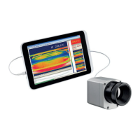
Details the main elements and features of the TIM Connect software interface.
Highlights key features of TIM Connect software, including extensibility and customization.
Explains the fundamentals of infrared radiation and its discovery.
Showcases various industrial and development applications of thermal imaging cameras.
Defines emissivity as a material constant describing the ability to emit infrared energy.
Provides three methods for determining the unknown emissivity of a surface.
Explains factors influencing emissivity and using emissivity tables for measurements.
Lists and describes various optional accessories for the thermoIMAGER TIM.
Provides detailed dimensional drawings for the CoolingJacket Advanced accessory.
Details the default factory settings of the thermoIMAGER TIM devices.
Presents typical emissivity values for various metallic materials.
Lists typical emissivity values for various non-metallic materials.
Describes the optional industrial process interface and its connections.
Explains options for extending USB cable length for greater distances.
Introduces serial communication capabilities and setup for TIM Connect software.
Explains DLL communication (IPC) for process imager device integration.
Introduces the Resource Translator tool for localizing the TIM Connect application.
Details the analog and digital inputs/outputs of the process interface.
| Detector Type | Uncooled microbolometer |
|---|---|
| Operating Temperature | 0 °C to +50 °C |
| Power Supply | USB powered / 5-36VDC |
| Storage Temperature | -40 °C to +70 °C |
| Encapsulation | IP67 |
| Interface | USB |
| Lens Options | Various lenses available (FOV depends on lens) |
| IP Protection | IP67 |