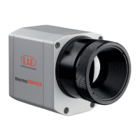
thermoIMAGER TIM
Appendix
A 1 Optional Accessories ............................................................................................................. 62
A 2 Dimensions Cooling Jacket Advanced ................................................................................. 65
A 2.1 Standard Version ........................................................................................................................................... 65
A 2.2 Extended Version ........................................................................................................................................... 66
A 2.3 Laminar Air Purge for Cooling Jacket ........................................................................................................... 67
A 3 Factory Settings ..................................................................................................................... 68
A 4 Emissivity Table Metals .......................................................................................................... 69
A 5 Emissivity Table Non Metals .................................................................................................. 72
A 6 Industrial Process Interface (Optional) ................................................................................. 74
A 6.1 Examples for a Fail-Safe Monitoring of the TIM with a PLC .......................................................................... 76
A 7 USB Cable Extensions ........................................................................................................... 78
A 8 A Brief Overview to Serial Communication........................................................................... 80
A 8.1 Introduction .................................................................................................................................................... 80
A 8.2 Setup of the Interface .................................................................................................................................... 80
A 8.3 Command List ............................................................................................................................................... 80
A 9 A Brief Overview to DLL Communication (IPC) .................................................................... 81
A 10 thermoIMAGER TIM Connect Resource Translator .............................................................. 82
A 11 Process Interface ................................................................................................................... 83
A 11.1 Analog Output ................................................................................................................................................ 83
A 11.2 Digital Input .................................................................................................................................................... 83
A 11.3 Analog Input (Usable Voltage Range: 0 ... 10 V) .......................................................................................... 84
A 11.4 Relay Output at Industrial PIF (Part No.: TM-PIFCxx-TIM) ............................................................................ 85

 Loading...