39
Anhydrous Ammonia (cont.)
Installation (cont.)
PLUMBING (cont.)
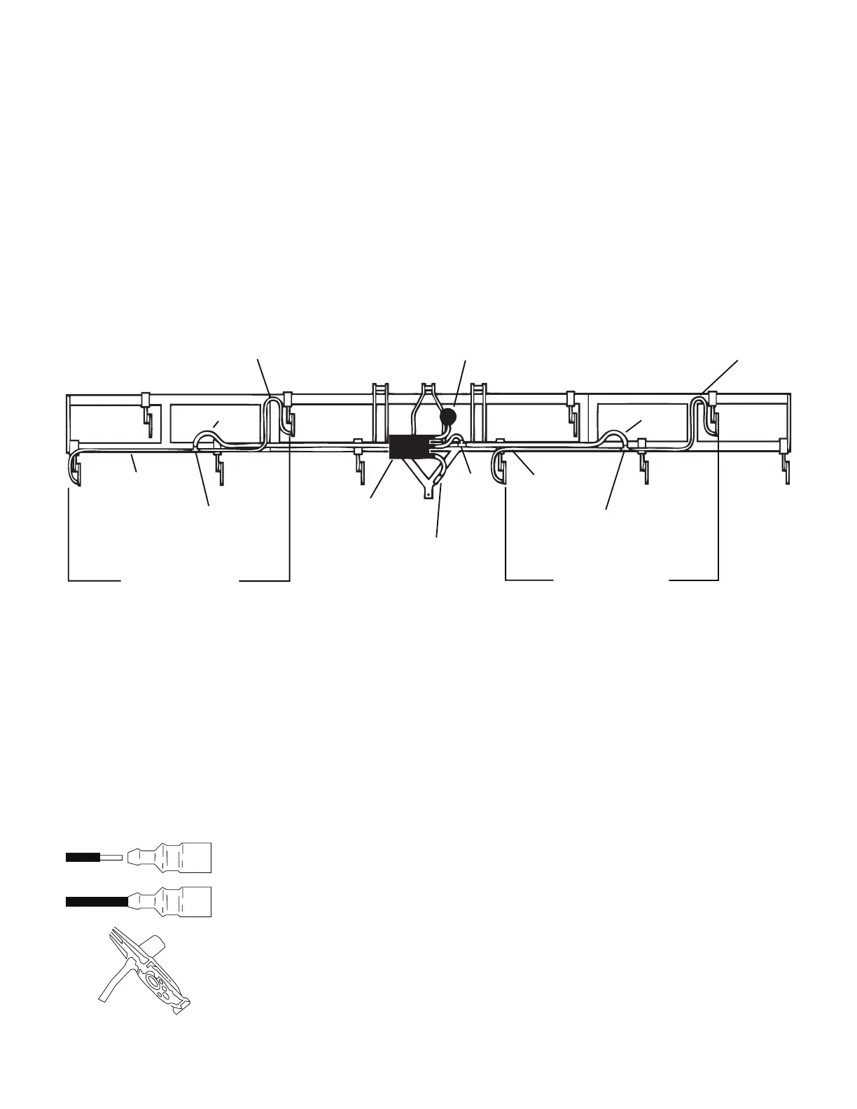
Connect ½” EVA hose to an outside vapor tube and route
along the applicator frame to the next vapor tube. Allow
extra hose to minimize kinking at hinge points. Cut to length
(make sure enough hose is left for other side) and attach the
hose to the second vapor tube. Install a ½” x ½” x ¾” tee
about halfway along this hose. Repeat for the other side.
Connect the tees using an appropriate length of ¾” EVA hose
routed along the frame. Install a ¾” tee about halfway along
this hose. Connect a ¾” hose to the tee and route to the
hose barb on the heat exchanger. Cut to length and install.
Secure all hoses with properly sized hose clamps. Attach the
hoses to the frame with cable ties
NOTE: NEVER USE THE MT-3000 CONSOLE PRESSURE
GAUGE WITH ANHYDROUS AMMONIA.
This gauge contains brass and is not compatible with NH
.
It is unsafe to bring any equipment containing NH
into the
operator’s area. Use a gauge approved for NH
installed on
the applicator’s manifold.
½” Vapor Hose
Breakaway
Coupler
NH3500 Kit
Steel Vapor Tubes
½” Vapor Hose
Manifold
½” Vapor Hose
½” Vapor Hose
¾” Vapor Hose
½” X ½” X ¾” Tee
¾” Tee
½” X ¾” X ½” Tee
Steel Vapor Tubes
¾” Vapor Hose
INSTALLATION OF VAPOR TUBES
ELECTRICAL
The NH3500 main wiring harness is made specifically for use
on anhydrous ammonia applicators. The harness combines
the wires for the servo valve, flowmeter and shut-off valve
into a single six pin connector.
The cable to the battery includes a user installed 7 ½ amp
fuse and fuse holder. Install the fuse holder (see illustration)
on the orange (hot) lead near the battery cable has been cut
to length. See the console operator’s manual for additional
power cable wiring details.
INSTALLATION
STEP 1
STEP 2
STEP 3
1. Strip insulation from wire
(approximately 3/8”/1 cm).
2. Insert wire in holder.
3. Crimp terminal through
body.*
4. Insert fuse.
5. Snap housing together.
* Recommended Crimping
Tools:
Thomas & Betts No. WT-1300
Radio Shack No, 64-40
General Electric - US & Metric Electrical
Terminal Tool.
Plug the main harness six pin connector into the Hold Cutout
Module which should already be connected to the plumbing
unit harness. Optional extension cables are available. Use
black plastic ties to secure the Hold Cutout Module to the
applicator.
NOTE: Remote Run/Hold is not available on the NH
systems.
Connect the heat exchanger’s blue wire to an unpainted
location on the applicator frame with a ¼” ring terminal.
Connect one end of the roll of blue wire to the applicator’s
frame with a ¼” ring terminal. Route this wire to the hitch
area and connect a male .250 connector. Perform a similar
operation on the tractor, terminating the wire with a female
.250 connector. Connect the blue wires together at the
hitch.