Portaflow 220 User Manual 7
(Issue 1.0)
2: Installation
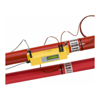
2.1 Transducer Positioning
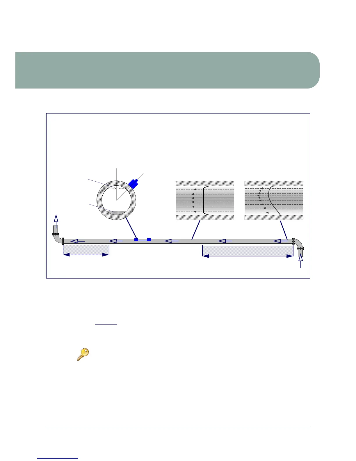
Figure 2.1 Locating the transducers
To obtain the most accurate results the condition of both the liquid and the pipe wall must be suitable to allow
the ultrasound transmission along its predetermined path. It is important also that the liquid flows uniformly
within the length of pipe being monitored and that the flow profile is not distorted by any upstream or
downstream obstructions. This is best achieved by ensuring there is a straight length of pipe upstream of the
transducers of at least 20 times the pipe diameter and 10 times the pipe diameter on the downstream side, as
shown in Figure 2.1
. Flow measurements can be made on shorter lengths of straight pipe, down to 10
diameters upstream and 5 diameters downstream, but when the transducers are positioned this close to any
obstruction the resulting errors can be unpredictable.
Key Point: Do not expect to obtain accurate results if the transducers are positioned
close to any obstructions that distort the uniformity of the flow profile.
Flow
Valid transducer location
10 x Diameter 20 x Diameter
45°
The Portaflow equipment expects a uniform flow profile as a
distorted flow will produce unpredictable measurement
errors. Flow profile distortions can result from upstream
disturbances such as bends, tees, valves, pumps and other
similar obstructions. To ensure a uniform profile the
transducers must be mounted far enough away from any
cause of distortion such that it no longer has an effect.
Uniform Flow Profile Distorted Flow Profile
In many applications an even flow velocity profile over
a full 360° is unattainable due, for example, to the
presence of air turbulence at the top of the flow and
possibly sludge in the bottom of the pipe. Experience
has shown that the most consistently accurate results
are achieved when the transducer guide rails are
mounted at 45° with respect to the top of the pipe.
Possible
sludge
Air
Flow
Guide
rail