1: General Description
4 Portaflow 220 User Manual
(Issue 1.0)
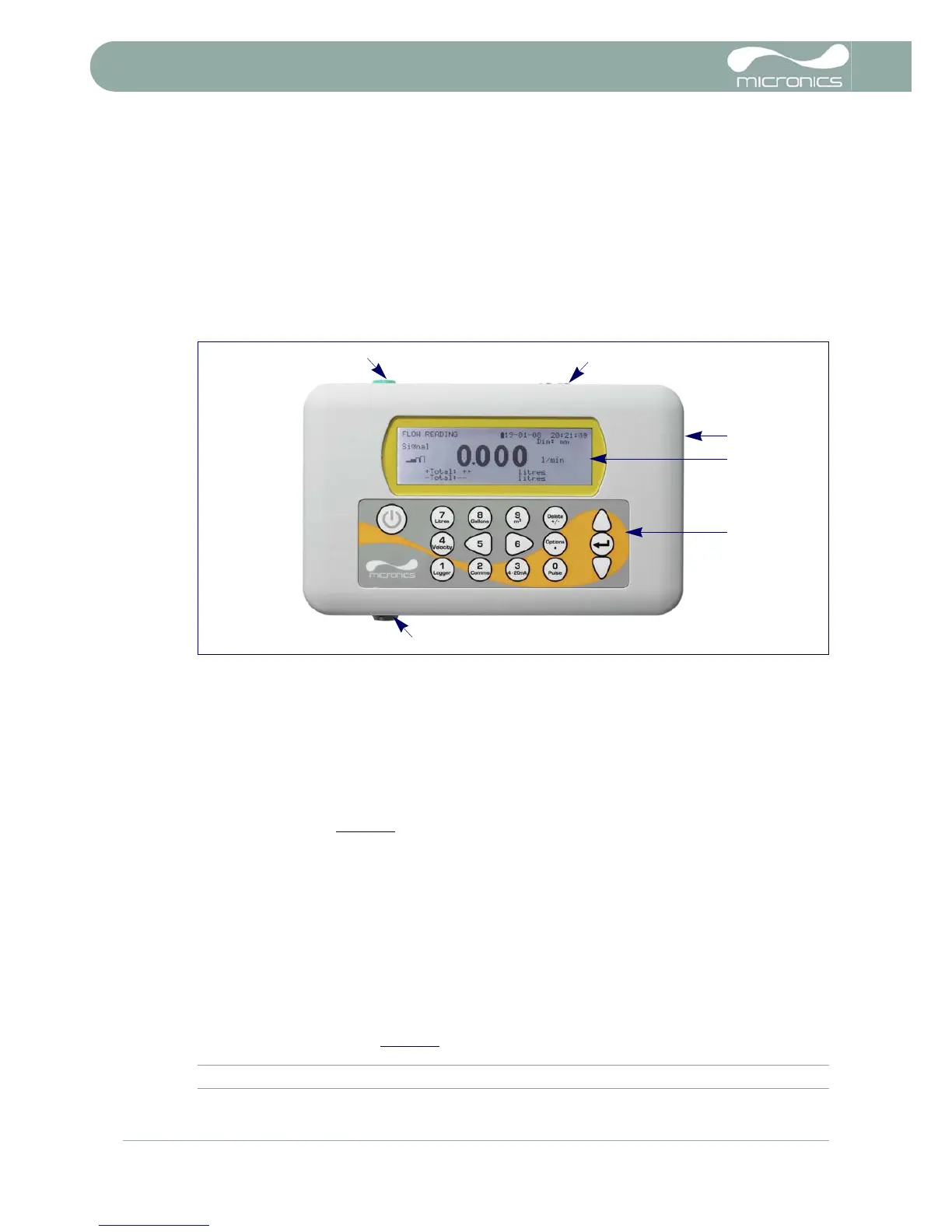
1.4 Portaflow 220 Instrument
The Portaflow 220 is a microprocessor controlled instrument operated through a menu system using an
inbuilt LCD display and keypad. It can be used to display the instantaneous fluid flow rate or velocity, together
with totalised values.
The instrument can also provide a current or variable ‘pulse’ output proportional to the detected flow rate.
These outputs, which can be used with a range of external interface devices such as those found in building
management or site monitoring systems, can be calibrated to suit a particular flow range.
1.4.1 Connectors
Figure 1.3 Instrument details
Transducer connections
The transducers are connected to two colour-coded miniature coaxial sockets located on the top of the
instrument. Using the red/blue connector cables provided, the upstream transducer should always be
connected to the RED socket and the downstream transducer to the BLUE one for a positive flow reading. It
is safe to connect or disconnect the cable while the instrument is switched on.
4-20mA and Pulse output connection
The 4-20mA / ‘pulse’ output cable should be connected to the green 7-pin connector on the top of the
flowmeter, as shown in Figure 1.3
. A single cable that can be adapted for use for either of these output
functions is included in the Portaflow 220 kit. The ‘tails’ on the free end of the cable must be terminated to suit
the intended application.
Red – 4-20mA positive
Black – 4-20mA negative
White – Pulse output
Green – Pulse return
Brown – Set Point (not in present use)
Blue – Set Point return (not in present use)
Thick Black – Cable screen
Battery charger connection
The supplied battery charger is connected to the instrument by means of the grey 2-pin connector on the
bottom of the unit, as shown in Figure 1.3
.
Note: The above connectors have different key-ways to prevent incorrect cable connection.