3: Operating Procedures
24 Portaflow 220 User Manual
(Issue 1.0)
4-20mA Signal scaling
Note: The 4-20mA can be set to represent a particular flow range. It is also possible to enter a negative figure
for the minimum output and this would enable a reverse flow to be monitored.
10. Select Output mA for error and enter a value (max of about 23mA) that you want the 4-20mA output
to produce in the event of an error (e.g. if the flow-rate is outside the set range).
11. Upon completion press ENTER to return to the FLOW READING screen.
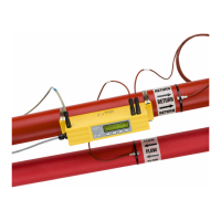
3.7.3 How to convert the measured current to flow rate
Assume the maximum flow rate is F
max
(l/min) and the minimum flow rate F
min
is ‘0’ (l/min), as shown.
To calculate the flow rate (l/min) for a measured current I(mA) then:
5. With the meter still connected to the 4-20mA
output adjust the Scroll keys to obtain an
output of exactly 20mA.
The DAC should indicate approximately
40000.
6. Press ENTER when done.
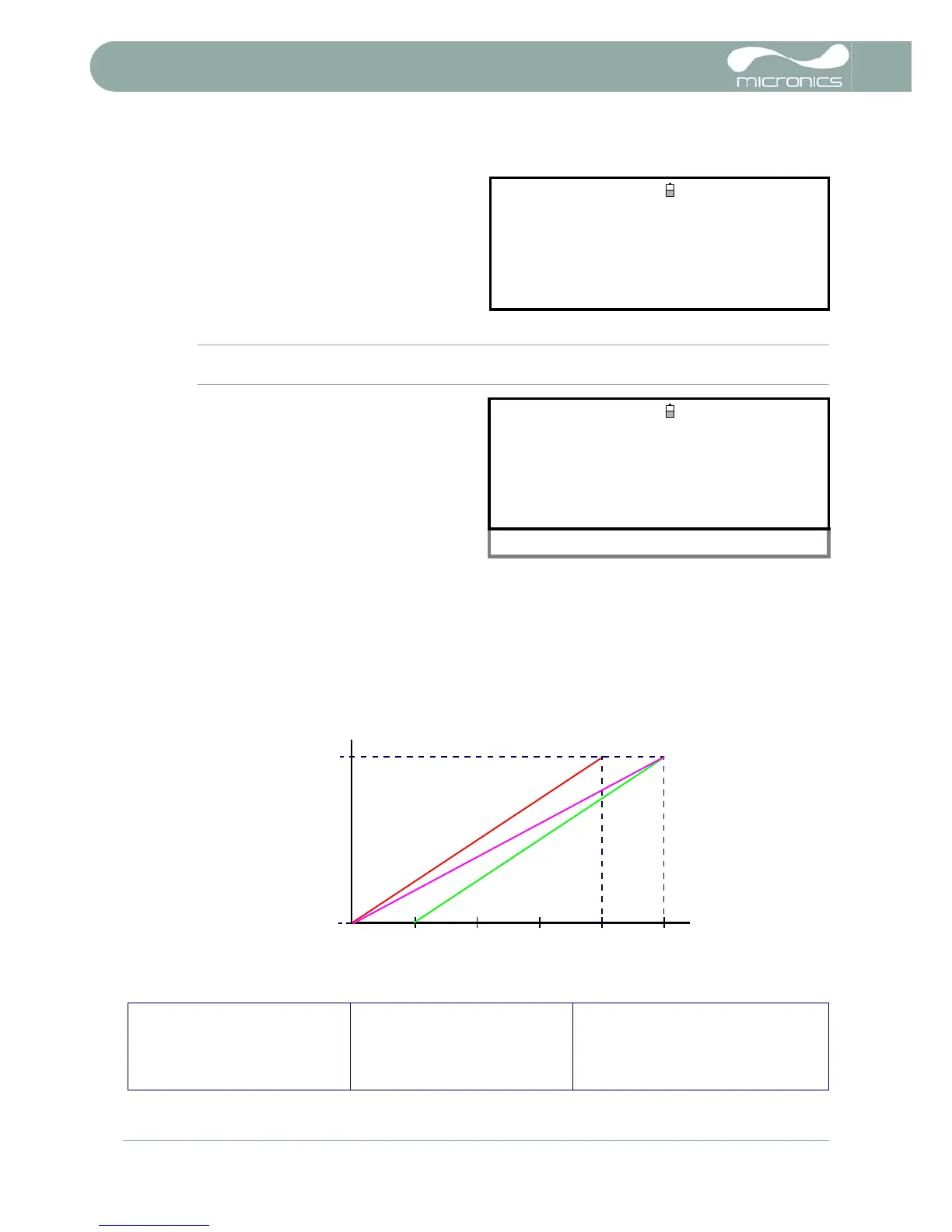
CALIBRATE 20mA
DD-MM-YY HH:MM:SS
Dim: mm
Adjust the output current to 20mA
Use
UV to set, 5/6 to trim
DAC Value: 40000
Press
when done
7. With the instrument operating in the FLOW
READING mode, press the 4-20mA function
key. This will access the 4-20mA OUTPUT
screen.
8. Select Flow at max. output and enter a
value of the flow rate that you want to
associate with a 20mA output.
9. Select Flow at min. output and enter a
value of the flow rate that you want to
associate with a 4mA output.
This could be ‘0’.
4-20 mA OUTPUT
DD-MM-YY HH:MM:SS
4-20 mA O/P is ON
Dim: mm
mA Output Reading : 0.00
Output Range : 4-20
Units : l/min
Flow at max. output : 0.00
Flow at min. output : 0.00
Output mA for error : 22.00
Exit
0-20mA 0-16mA 4-20mA