DOC 6501_Release V
ATS-6501 Users Guide
11
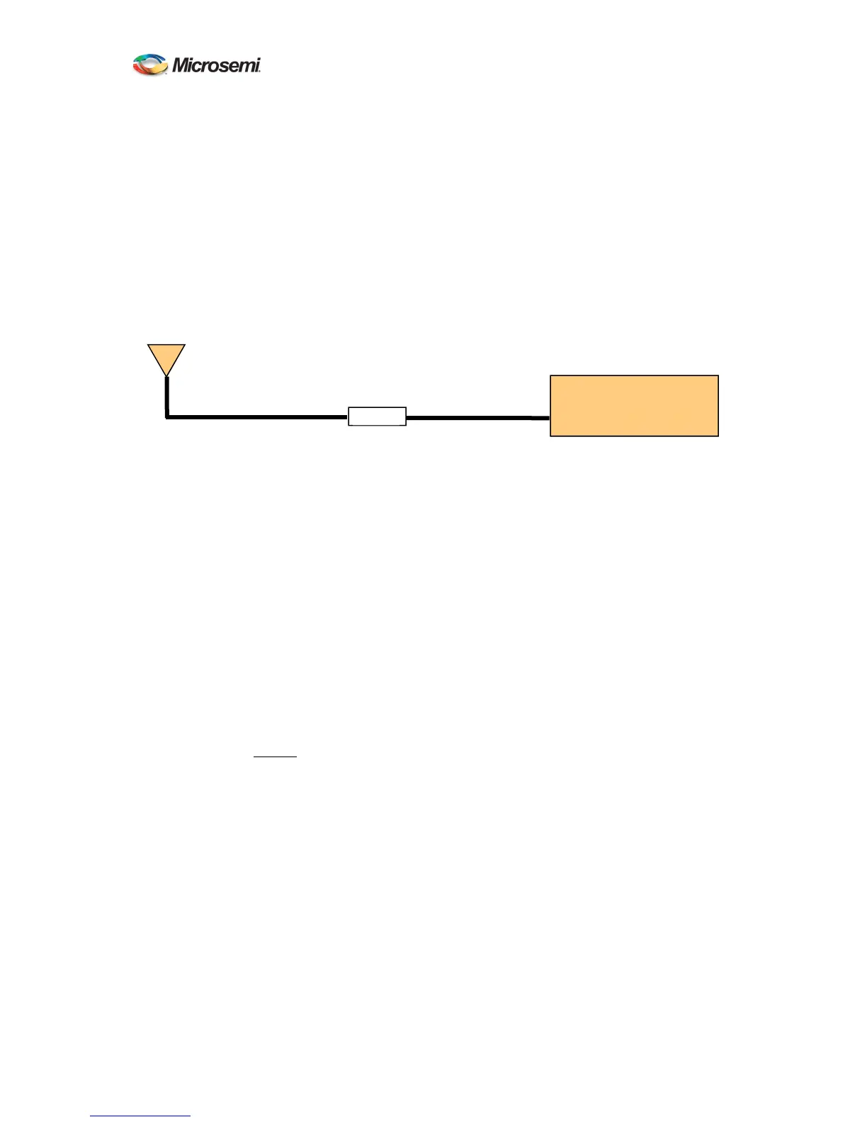
G. Placement of the line amplifier is also a concern in a properly designed system. Placing
the amplifier too far from the antenna may cause unexpected degradation in the GPS
signal and the performance will remain poor. The best place for the amplifier is typically
half way between the antenna and ATS-6501. This allows the line amplifier to benefit
from any surge protection that may be installed near the antenna but is still close enough
to the antenna so as not to degrade the signal significantly. Figure 2 shows the block
diagram of a typical installation that requires a longer antenna cable. Another
consideration when installing the line amplifier is how it will receive power. Some
amplifiers are powered using a DC bias on the antenna cable and others are power from
AC adapters directly. Please contact Microsemi if you require assistance in selecting the
right amplifier for your application.
The antenna mount should be secured to a stable structure such as a building, antenna
mast, or other suitable mounting platform.
H. The antenna is designed to withstand rain, snow, and dust. When selecting the mounting
location for the antenna try to find a location that will not become buried in snow and/or
covered by foliage. Keep the top surface of the antenna clean and brush off any ice and
snow, to ensure your antenna performs optimally. In addition, ensure the connector
remains clean and dry.
2.3.2 Setting the Antenna Voltage
The ATS-6501 is capable of providing antenna power (0, 5, 12VDC) by DC biasing the antenna
cable but this can cause damage to an antenna if the wrong voltage is applied. Prior to connecting
an antenna to the unit, ensure the antenna voltage is set properly. The ATS-6501 is shipped from
the factory with the default antenna voltage of 0 volts. If this is not the desired configuration then
follow the steps below to set the proper antenna voltage.
A. Telnet into the system command port telnet ip addr 1700 or connect via the USB Port and
the command prompt should appear.
B. At the command prompt, type settings gps and press enter, this will display the user
configurable GPS settings for the unit to see verify the current voltage being supplied to
the antenna
ATS-6501>settings gps
[antenna_delay] 2.277000000000000e-07
[antenna_voltage] 1.200000000000000e+01
[datum] wgs84
[mask_angle] 1.000000000000000e+01
ATS 6501
Line Amp
Figure 2 Antenna Cable
ANTENNA
 Loading...