DOC 6501_Release V
ATS-6501 Users Guide
55
3 Operations
Two distinct tasks are performed by the ATS-6501 1) collection of GPS measurement data 2) the
generation of timing signals. These two tasks are entirely separate except for the fact that they
must share CPU time and data from the GPS receiver. Because the generation of timing signals
requires that events (e.g., clock steering) occur at very specific times, operational precedence is
always given to timing tasks. As a result, any operations concerning the collection and storage of
GPS data are postponed until all timing operations have been completed.
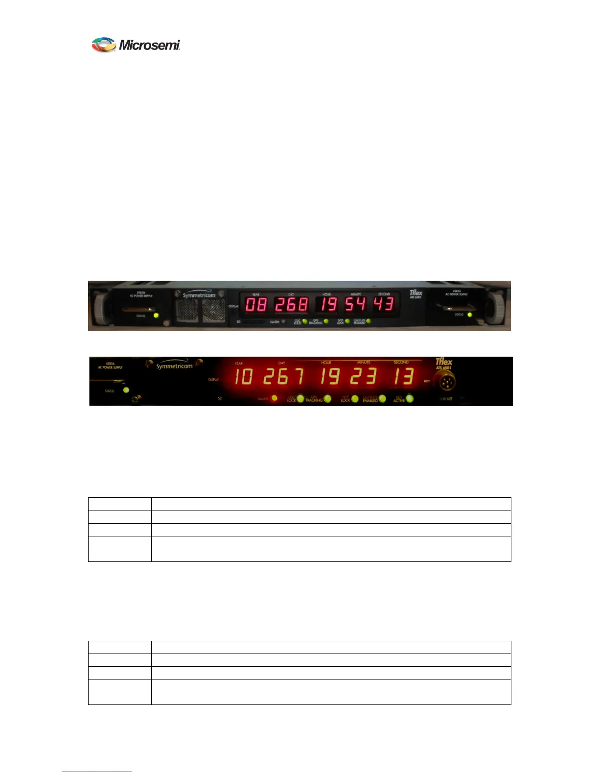
3.1 Front Panel
The ATS-6501 has several front panel indicators to provide the operator with the overall status of
the unit as well as a visual alarm indication if a problem with the hardware or the unit detects a
condition that would cause the output signals to be outside of their timing specifications. More
detailed status information can be retrieved using the status command on the Command Port.
Figure 7 ATS-6501 Front Panel
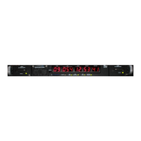
Figure 8 ATS-6501 SAASM Front Panel
3.1.1 Power Supply Indicators
Each power supply has a front panel indicator that provides the operator an instant visual
indication of the supply status. Power Supply #1 is on the left, power supply #2 is on the right as
viewed from the front.
Indicator Status
Off No power is being provided to the ATS-6501.
Green Power supply is good and is supplying power.
Red ATS-6501 has power and the module has failed, is not seated properly, or is
unplugged from the power source.
Table 1 Power Supply Indicator Status
3.1.2 Alarm Indicator
The Alarm LED will turn red when the unit is not producing timing within their specifications or
the system has suffered a major hardware failure.
Indicator Status
Off Unit has no current alarms.
Green This indicator should only turn green during the front panel POST.
Red Either power supply is missing/has failed or is without input power.
Any output module(s) is reporting a failure