DOC 6501_Release V
ATS-6501 Users Guide
59
ATS-6501>settings hardware
[enable_fp_button] false
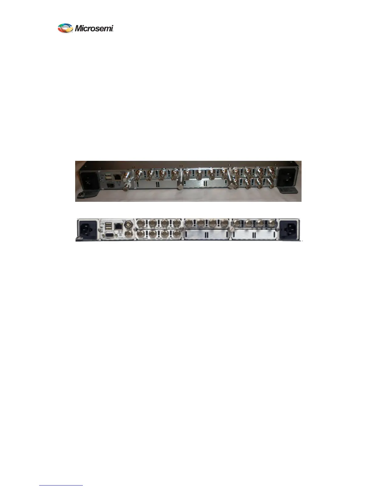
3.2 Rear Panel
All hardware interfaces and connectors with the exception of the Crypto Key (SAASM Model)
are located on the rear panel of the ATS-6501. The system can provide eight types of output
timing signals: 1 PPS, 10 MHz, 5MHz, 1MHz, DC IRIG, AM IRIG, NASA36, and the ATS-
6511 reference signals depending on which output modules are installed and the system
configuration settings. Each output module has four connectors. These outputs can be used to
directly feed other instruments or feed a distribution system that provides any number of user
outputs. The on-time-point (OTP) of the system is typically at the output of the BNC connectors
(Section 2.5) but it can be adjusted to be any point in an integrated system by accounting for
distribution delays and adjusting the antenna delay value (Section 2.6).
Figure 9 ATS-6501 Rear Panel
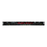
Figure 10 ATS-6501 SAASM Rear Panel
Under normal operations the only inputs required for operation of the ATS-6501 are at least one
power source and a GPS Antenna. GPS is the source of time (UTC) for the unit and the ATS-
6501 will not start up normally without it. Once at least four satellites have been acquired the
unit will continue to output timing signals even when the GPS antenna is removed. However, the
accuracy of these outputs will degrade over time.
Users can start the system up without GPS using an external reference (another ATS-6501, an
ATS-6502, or Time Interval Counter). See Appendix E.
Connection to a local area network (LAN) is supported by the ATS-6501. This allows users to
access the unit remotely and also provides error monitoring capabilities. In addition, the ATS-
6501 can serve as the source of network time for other systems on the network if using network
time protocol (NTP). The system can only support ~100 NTP users. The USB ports can be used
in conjunction with a USB-to-Serial conversion cable to allow users access to the command port
via a local terminal and/or allows the system to communicate with an external reference (5071A).
The GPS Antenna connector is used to connect the GPS Antenna to the system. The 10MHz IN
connector is used to provide the 10MHz signal input from an external frequency reference. See
Figure 11.