24 Port Gigabit Ethernet PoE Switch – User Manual Page 8 of 72
________________________________________________________________________
©2014 MICROSENS GmbH & Co. KG – Hamm/Germany www.microsens.com
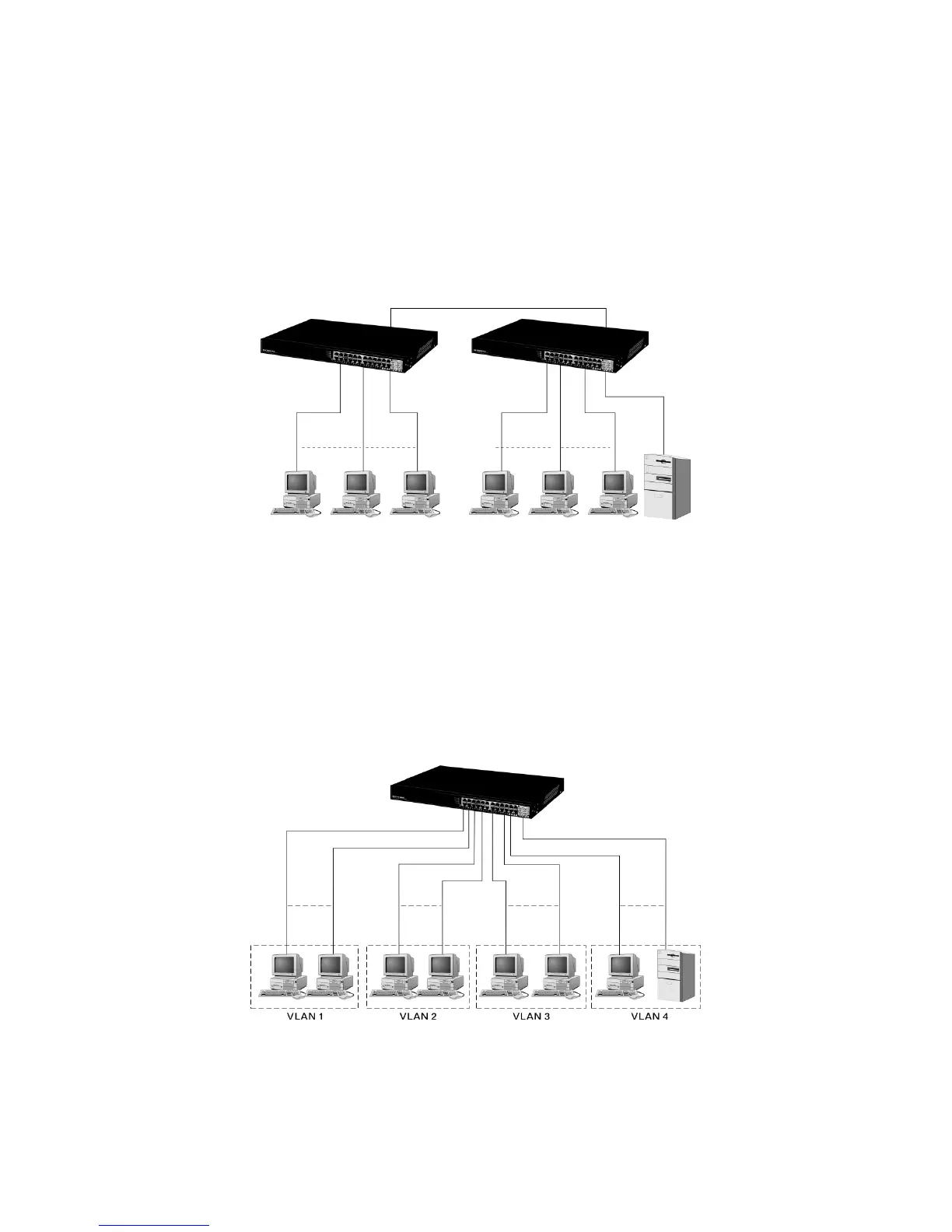
• Typical Network Topology in Deployment
A hierarchical network with minimum levels of switch may reduce the timing delay
between server and client station. Basically, with this approach, it will minimize the num-
ber of switches in any one path; will lower the possibility of network loop and will im-
prove network efficiency. If more than two switches are connected in the same network,
select one switch as Level 1 switch and connect all other switches to it at Level 2. Serv-
er/Host is recommended to connect to the Level 1 switch. This is general if no VLAN or
other special requirements are applied.
Case1: All switch ports are in the same local area network.
Every port can access each other (See Fig. 2-2) *
Fig. 2-2 No VLAN Configuration Diagram
If VLAN is enabled and configured, each node in the network that can communicate
each other directly is bounded in the same VLAN area.
Here VLAN area is defined by what VLAN you are using. The switch supports both
port-based VLAN and tag-based VLAN. They are different in practical deployment, espe-
cially in physical location. The following diagram shows how it works and what the differ-
ence they are.
Case2a: Port-based VLAN (See Fig.2-3).
Fig. 2-3 Port-based VLAN Diagram
1. The same VLAN members could not be in different switches.
2. Every VLAN members could not access VLAN members each other.
3. The switch manager has to assign different names for each VLAN groups at one
switch.