Certified Drawing
IM 613 / Page 11 (Rev. 7/99)
The following commissioning procedures pertain to unit ventila-
tors equipped with the MicroTech Unit Ventilator Controller (UVC).
These procedures must be performed in addition to the mechanical
and electrical system commissioning procedures that are
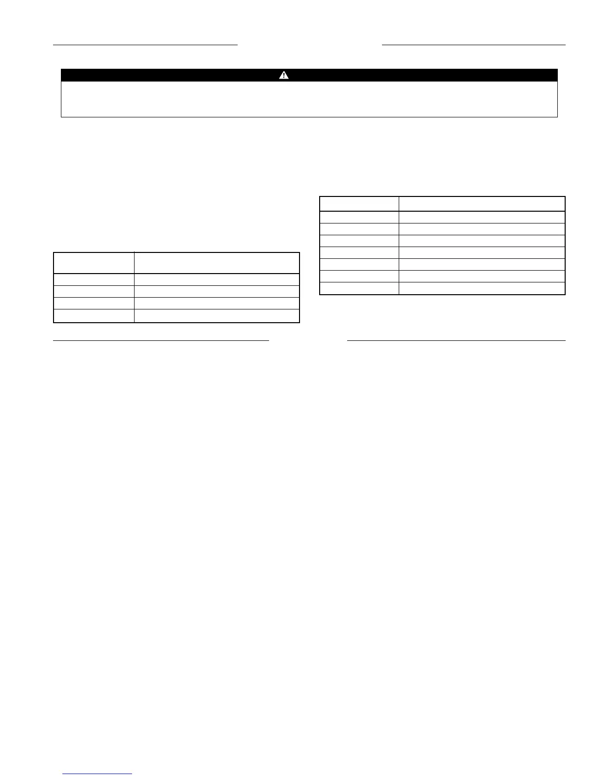
outlined in the model-specific installation literature. Table 5
provides a listing of this literature.
Caution: Before power is applied to any unit, the pre-start
procedures in the model-specific installation literature must be
closely followed.
WARNING
ELECTRICAL SHOCK HAZARD! Could cause severe injury or death. Failure to bond the frame of this equipment to the
building electrical ground by use of the grounding terminal provided or other acceptable means may result in electrical shock.
Service must be performed only by qualified personnel.
A large part of the commissioning procedure is ensuring that the
unit ventilator operates according to its programmed sequence
of operation. The unit ventilator sequences of operation are
described in the program-specific literature listed in Table 6.
Commissioning
Unit Ventilator Installation & Maintenance
Model Data Bulletin Number
AE UV-3-204 (IM 502)
AZ UV-3-205 (IM 503)
AR UV-3-202 (IM 504)
AV/AH UV-3-200 (IM 506)
Table 5. Model-Specific Unit Ventilator Installation Literature
UVC Program Operation Manual Bulletin Number
UV1*** OM 101
UV2*** OM 102
UV3*** OM 103
UV4*** OM 104
UV5*** OM 105
UV6*** OM 106
UV7*** OM 107
Table 6. Program-Specific Sequence of Operation Literature
Pre-Start
Required Tools and Literature
The following tools and additional literature may be required to
properly commission a MicroTech UVC.
Tools:
1. Digital voltmeter
2. Digital ohmmeter
3. Digital thermometer
4. General technician’s tools
5. PC equipped with Monitor software (required for master/
slave and Network UVC, optional for stand-alone UVC’s)
Literature:
1. Model-specific unit ventilator installation bulletin (see Table
5)
2. Program-specific sequence of operation bulletin
(see Table 6)
Unit Ventilator Identification
The AAF-McQuay unit ventilators look similar; however, there are
significant internal differences which are defined by the model
number code string. In addition to the basic heating and cooling
equipment, the model number code string specifies which
factory-configured options have been provided. These options
determine the internal wiring configuration and the field
wiring requirements.
Obviously, it is extremely important that the correct unit
ventilator be placed in the correct location in accordance with job
requirements. Proper unit ventilator location should have been
determined during the installation process. Nevertheless, proper
location must be verified during the commissioning process.
Know Your Unit Ventilator
Before commissioning can proceed, the start-up technician must
know which options are supposed to be present on a particular
unit ventilator.
1. Check the model number code string against the job
requirements. Refer to the unit-specific installation bulletin
for a guide to model number nomenclature.
2. Check the program and software model numbers against
the unit model number code string. The UVC software must
be compatible with the unit ventilator configuration. Refer
to the “Software ID” section of this manual.
Note: If a PC is being used for commissioning, check the
software ID using the Monitor program. The controller’s
program is identified on one of the display screens.
Field Wiring Check
The unit ventilator factory-configured options determine the low
voltage field wiring requirements. If a specific option is present
on a particular unit ventilator (as denoted by the model number),
the associated field wiring (if any) must be checked.
Detailed electrical installation instructions and field wiring
diagrams are included in the model-specific installation literature
supplied with each unit ventilator. Referring to this literature and
using the following check lists, the start-up technician should
thoroughly check the electrical installation before the
commissioning process proceeds.
Wall Sensor Packages
1. Check that the cable is twisted and shielded.
2. Check that the required number of conductors are available.
3. Check that the shield is grounded in accordance with the
installation literature.