Certified Drawing
IM 613 / Page 7 (Rev. 7/99)
Compressor Short-Cycle Protection
All compressor-equipped unit ventilator models (self-contained
or split system) include compressor short-cycle protection.
When a compressor is energized, it will remain energized for at
least 2 minutes before the temperature control sequence will be
allowed to de-energize it. An alarm condition can override this
“minimum-on” timer and stop the compressor if necessary.
When a compressor is de-energized, it will remain
de-energized for at least 3 minutes before the temperature
control sequence will be allowed to energize it again.
Low Ambient Lockout
Except for the water source heat pump (WSHP) models, all
compressor-equipped unit ventilators (self-contained or split
system) include compressor low ambient lockout protection.
This feature will prevent compressor operation when the unit is in
the cooling mode and the outdoor air temperature is below 59°F.
Random Start
A random start feature is provided with all compressor-equipped
unit ventilators (self-contained or split system). This feature will
prevent simultaneous compressor start-up that could otherwise
occur after the following events:
• Unit power-up
• Unoccupied to occupied changeover
• Brownout condition
The compressor start delay can be from 1 to 63 seconds and is
determined by the UVC hex switch setting. For more information,
refer to “Hex Switches” in the “Component Data” section of this
manual.
Delayed Reversing Valve De-energization
All heat pump unit ventilator models have a 60-second (default)
reversing valve de-energization delay feature.
This delay prevents the reversing valve from returning to its
normal (cooling) position for a period of 60 seconds after the
compressor is de-energized when the unit is in the heating mode.
If necessary, an alarm condition can override the 60-second timer
and de-energize the reversing valve with the compressor.
Emergency Heat
All heat pump unit ventilator models that are equipped with
electric heat have an emergency heat feature.
The emergency heat mode is initiated by depressing the
momentary, unit-mounted emergency heat switch. When the unit
is in the emergency heat mode, the following actions occur:
• Compressor is immediately de-energized and locked out.
• Reversing valve is de-energized after a delay.
• Electric heat is staged to maintain the room heating
setpoint regardless of outdoor air temperature
(ASHP units) or entering water temperature (WSHP units).
The unit ventilator may be returned to normal operation by
cycling power to the controller (use fan switch or main
power switch).
ASHP Units Only: Note that the emergency heat switch (SW5)
and defrost control contacts are wired in parallel and use the
same UVC digital input (DI-3). The emergency heat switch
provides a momentary contact closure and the defrost control
provides a maintained contact closure. Therefore, do not hold
the emergency heat switch down or the unit may enter the
defrost mode instead of the desired emergency heat mode.
Defrost
The AE air source heat pump (ASHP) unit ventilator models have
a defrost cycle which prevents frost from building up on the
outdoor coil when the unit is operating in the heating mode.
An external defrost control provides a maintained contact
closure to the UVC when defrost is required.
When the unit is in the defrost mode, the following
actions occur:
• Reversing valve is de-energized (unit enters “cooling” cycle).
• Electric heat is staged to maintain the room setpoint
regardless of outdoor air temperature.
• Compressor cannot be de-energized by room temperature
control until defrost mode ends.
For further information on the defrost control cycle, refer to
Bulletin No. OM 101, MicroTech Unit Ventilator Controller
Sequences of Operation: Program UV1.
Alarm Monitoring & Controlled Response
The MicroTech UVC is capable of sophisticated alarm
monitoring and controlled response functions. Each alarm
(or “fault”) is prioritized, indicated, and responded to with the
appropriate action. If multiple alarms are present, the alarm with
the highest priority is indicated.
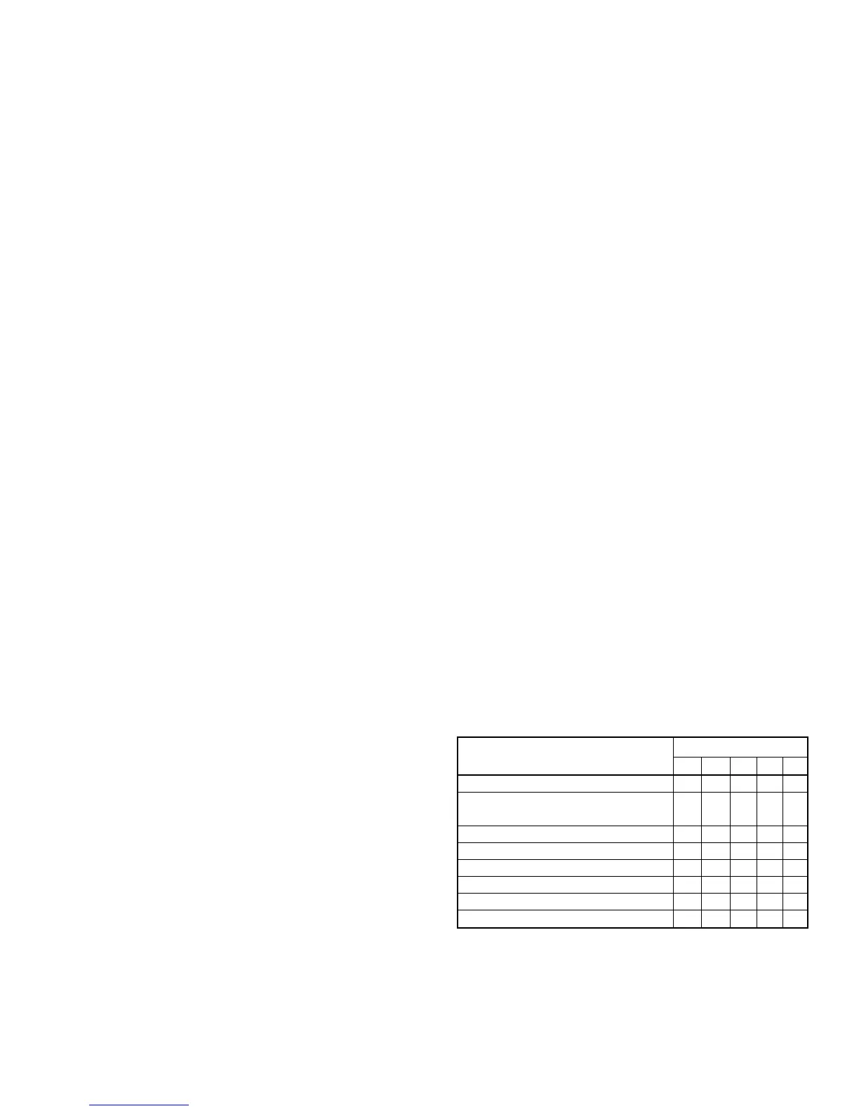
A summary of the available alarm features is shown in Table 3.
For more information, refer to the “Alarm Monitoring &
Control” section of this manual. Following are brief descriptions
of each feature.
Alarm & Controlled Response Feature
Unit Ventilator Model
AE AZ AR AV AH
Sensor Diagnostics (Each Sensor) • • • • •
Actuator Feedback Diagnostics
•••••
(Each Actuator)
Brownout Protection • • • • •
High Pressure • • •
Low Coil Temperature (DX and/or Water) • • • • •
Low Refrigerant Temperature (Water Coil) •
Communication Error (Master/Slave Only) • • • • •
Change Filter (Network Units Only) • • • • •
Table 3. Alarm & Controlled Response Feature Availability