IM 613 / Page 18 (Rev. 7/99)
Status LED
Alarm Description
Unit Ventilator Model
Blinks
(Fault)
Trigger Factory Setting Fault Reset
(Priority ` (Clear)
AED AZS ARQ AVS AHF
AEQ AZQ ERQ AVV AHV
● ● ● ● ●
● ● ●
● ● ● ● ● ●
●
● ● ● ● ● ● ● ●
● ● ● ● ● ●
● ● ● ● ● ● ●
● ● ● ●
● ● ● ● ● ●
● ● ● ● ●
● ● ● ● ●
● ● ● ● ●
● ● ● ● ● ● ● ● ● ●
● ● ● ● ● ● ●
● ● ● ● ●
● ● ● ● ●
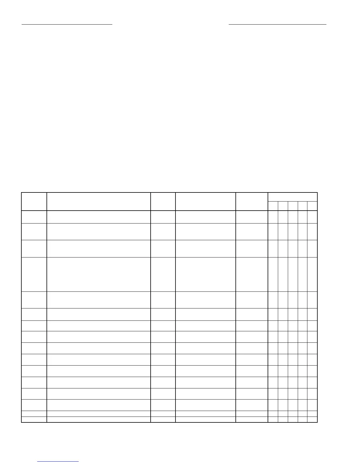
2 Room Temperature Sensor Failure Software Outside Range:
0.39 to 4.88 VDC (±4%)
3 High Pressure Hardware Opens at 400 ± 10 psig 2-Auto resets
(HP) Closes at 300 ± 20 psig within 7-days
then Manual
3 Low DX Coil Temperature (Units with Wet Heat) Hardware Opens at 30 ± 4°F 2-Auto resets
(T4) Closes at 50 ± 6°F within 7-days
then Manual
4 Low Refrigerant Temperature (Water Coil) Hardware Standard Range: 2-Auto resets
(T2) Opens at 36 ± 3°F within 7-days
Closes at 46 ± 2°F then Manual
Extended Range & Ground
Opens at 25 ± 3°F
Closes at 35 ± 2°F
5 Low DX Coil Temperature (Units without Wet Heat) Hardware Closes at 30 ± 4°F 2-Auto resets
(T4) Opens at 50 ± 6°F within 7-days
then Manual
5 Low Water Coil Leaving Air Temperature Hardware Closes at 38 ± 2°F
(T6) Opens at 45 ± 2°F Auto
6 Brownout Software Line Voltage < 85% Auto
of Nameplate Voltage (after 5 min)
7 Heating Valve Position Feedback Failure Software Outside Range:
0.2 ± 0.1 to 3.68 ± 0.29 VDC Auto
8 Valve or F&BP Damper Position Feedback Failure Software Outside Range:
0.2 ± 0.1 to 3.68 ± 0.29 VDC Auto
9 OA Damper Position Feedback Failure Software Outside Range:
` 0.2 ± 0.1 to 3.68 ± 0.29 VDC Auto
10 Discharge Air Temperature Sensor Failure Software Outside Range:
0.39 to 4.88 VDC (±4%) Auto
11 Outdoor Air Temperature Sensor Failure Software Outside Range:
0.39 to 4.88 VDC (±4%) Auto
12 Mixed Air Temperature Sensor Failure Software Outside Range:
0.39 to 4.88 VDC (±4%) Auto
13 Water-In Temperature Sensor Failure Software Outside Range:
0.39 to 4.88 VDC (±4%) Auto
15 Change Filter (Network Units Only) Software Fan Runtime Setpoint, Adj. Network
16 Communication Error (Master/Slave Only) Software N/A Auto
Diagnostics & Service
Table 9. Alarm and Fault Code Summary
Alarm is available for this unit.
Alarm may be available, depending on unit configuration.
●
●●
fault is present at a time, the status LED will indicate the one with
the highest priority. As the higher priority faults are cleared, the
lower priority faults will be indicated.
The UVC will simultaneously respond to multiple faults with the
appropriate control actions. If the programmed control actions of
multiple faults are contradictory, the higher priority fault actions
will occur. For example, assume that the 5-blink “low water coil
temperature” and 7-blink “heating valve position feedback
failure” faults exist concurrently. When the feedback failure fault
occurs, UVC control of the heating valve outputs is programmed
to cease (the valve would then hold its position). When the low
coil temperature fault occurs, the heating valve is programmed to
modulate to 25% open. In this situation, the 5-blink low coil
temperature alarm has higher priority. Therefore, the heating valve
will be opened. (Since there is no reliable feedback, the valve
could possibly open past the 25% setpoint.)
Clearing Faults
Before any fault can be cleared, the alarm conditions that caused
it must have returned to normal. When the alarm conditions are
gone, a fault may be cleared either automatically or manually.
Refer to Table 9.
Alarm Monitoring & Control
The Unit Ventilator Controller (UVC) is programmed to monitor
the unit ventilator for specific alarm conditions that may occur on
the various model types. If an alarm condition exists and is
| detected by the UVC, a “fault” will occur. The UVC will indicate
the fault and execute appropriate control actions for the alarm
conditions. For most faults, these actions will fail-safe the unit
ventilator.
Fault Code Interpretation
UVC faults are indicated at the status LED (on-board or remote).
If a fault exists, operating mode indication will be replaced by an
alarm-specific fault indication, the fault code.
A fault code is a series of blinks followed by a one-second pause.
The number of blinks identifies the alarm condition as shown in
Table 9. The fault code sequence will repeat continuously until
the fault is cleared.
Priority and Multiple Alarms
Faults are ranked in order of their priority. Higher priority faults
have lower fault code blink counts (see Table 9). If more than one