Certified Drawing
IM 613 / Page 5 (Rev. 7/99)
Status LED State Indication
On Continually Occupied Mode
On
1
⁄2 sec./ Off 5
1
⁄2 sec. Unoccupied Mode
On 5
1
⁄2 sec./ Off
1
⁄2 sec. Tenant Override Mode
Flashing* Alarm Condition
On 3 sec. / off 3 sec.** Calibration
on-board status LED. If used, the remote LED is connected to
the UVC at the terminal section labeled “LED.”
Power LED
The green, on-board power LED indicates microprocessor “on”
status. After applying power to the unit, the power LED should
illuminate continuously. For more information, refer to “Test
Procedures” in the “Service Information” section of this manual.
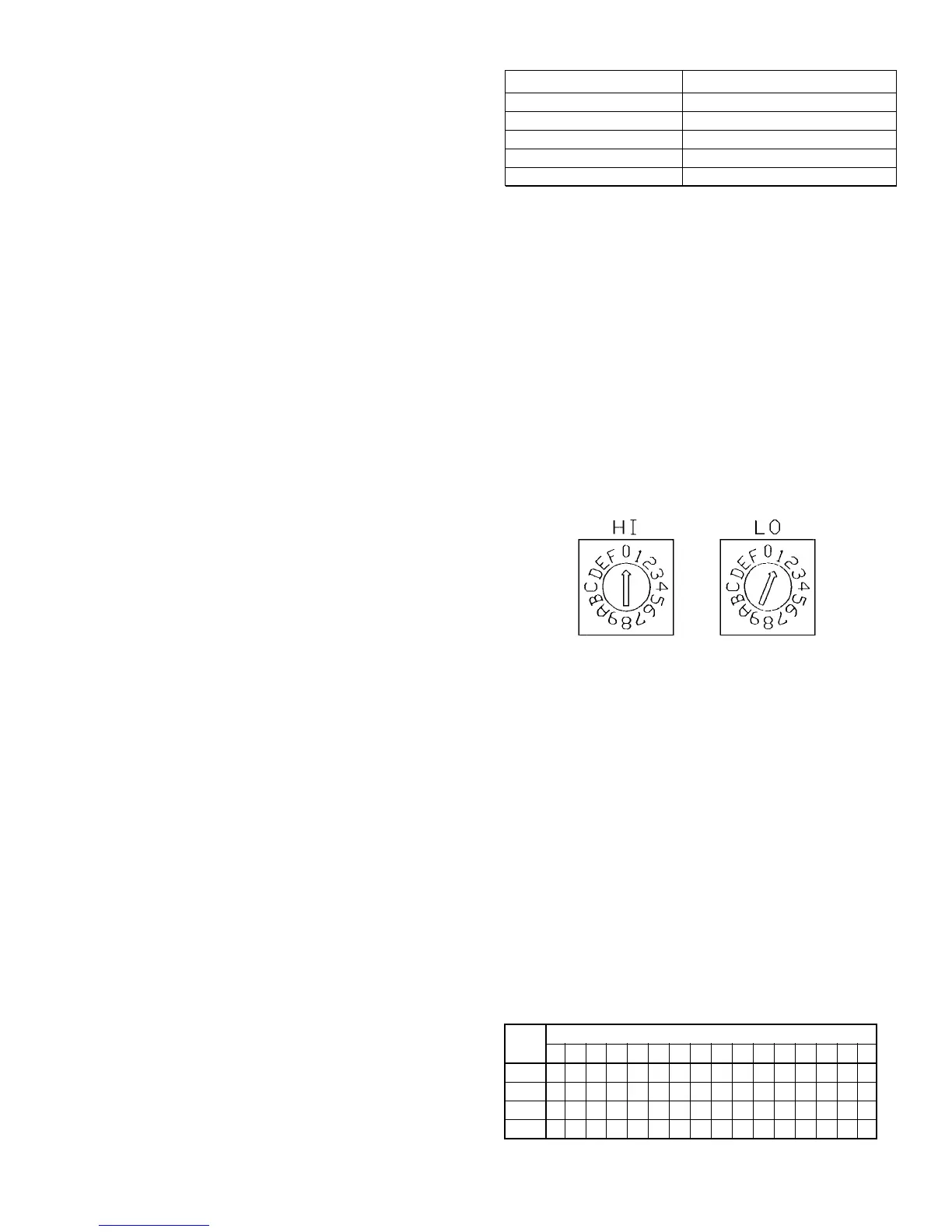
Hex Switches
The UVC includes two hex (hexadecimal) switches that may need
to be set. The HI and LO hex switches are shown in Figures 1
and 2. Table 2 provides a hex-to-decimal conversion guide.
A “hex switch setting” is defined as the HI switch digit followed by
the LO switch digit. For example, a hex switch setting of 2F would
have the HI switch set to “2” and the LO switch set to “F.”
Stand-alone Units
On compressor-equipped units (self-contained or split system),
the hex switch setting defines the random start delay period. Each
unit on a common circuit or time clock should have a different
hex switch setting to ensure that multiple units do not start
simultaneously. The settings may be between 01 and 3F.
If the unit ventilator has no compressor, leave the hex switch
setting at 01.
Master, Slave and Network Units
The hex switch setting defines the controller’s network address.
(If the master, slave or network unit has a compressor, the
random start delay is also defined by the hex switch setting.) For
more information on master/slave addressing, refer to “Master/
Slave” in the “Start-up” section of this manual. For more
information on MicroTech network addressing, refer to the
MicroTech Network Master Panel installation bulletin.
Microprocessor
The UVC contains a microprocessor that is preprogrammed with
the software required to monitor and control the unit. It receives
input data from as many as 20 inputs (analog or digital) and sends
commands to as many as 8 outputs (electromechanical relays).
(There are 2 additional solid-state relay “aux” outputs which are
not used for standard unit ventilator configurations.) The quantities
and types of inputs and outputs are dependent on the unit venti-
lator model type and configuration options. All input and output
connections to the UVC are made using insulation
displacement type (IDC) terminal connectors.
The UVC uses field-adjustable setpoints and fixed,
preprogrammed parameters to maintain unit control. (Many of
the preprogrammed parameters can be adjusted with a PC
equipped with Monitor software.)
Setpoint Adjustment Potentiometers
There are three setpoint adjustment potentiometers (pots) on
the UVC:
• Minimum outdoor air damper position pot
• Heating setpoint pot
• Unoccupied offset adjustment pot
Note: On slave and network controllers, these three setpoint
values are received via network communications, and the
pot settings are ignored. On slave controllers only, the
pot settings are used when communications are lost.
Therefore, it is recommended that appropriate “default”
pot settings be set for slave units.
Minimum Outdoor Air Damper Position Pot
The minimum position pot defines the minimum outdoor air (OA)
damper position. The OA damper is typically held at its minimum
position when cooling is not required or when the OA temperature
is not suitable for free cooling. Refer to the sequence of operation
document provided with your unit for more detailed
information.
Heating Setpoint Pot
The heating setpoint pot adjusts both the occupied cooling and
heating setpoints. The room occupied heating setpoint is shown
on the UVC faceplate. The room occupied cooling setpoint is
calculated by adding the deadband value to the heating setpoint
(deadband default = 6°F).
Unoccupied Offset Adjustment Pot
The unoccupied offset pot sets the offset value used to deter-
mine the unoccupied heating (or night setback) and unoccupied
cooling (or night setup) setpoints. The night setback setpoint is
calculated by subtracting the offset value from the occupied
heating setpoint. The night setup setpoint is calculated by adding
the offset value to the occupied cooling setpoint.
Status LED
An amber, on-board status LED aids in diagnostics by indicating
the unit ventilator operating mode and alarm conditions. If there are
no current alarm conditions, the LED will indicate the unit operating
mode as shown in Table 1. If there are one or more alarm condi-
tions present, the LED will flash in a specific sequence to indi-
cate a particular alarm condition. For more information on alarms,
refer to the “Alarm Monitoring & Control” section of this manual.
A remote status LED is provided with all optional wall- mounted
temperature sensor packages. It has the same function as the
Figure 2. Hex Switches
Table 1. Status LED Indication
* Refer to Table 9 in the “Alarm Monitoring & Control” section of this manual.
** Calibration of OA Damper, F&BP Damper, and/or valve actuators will be
completed within approximately 5-min after power-on.
HI Hex
LO Hex Digit
Digit 0123456789ABCDEF
0 0*123456789101112131415
1 16171819202122232425262728293031
2 32333435363738394041424344454647
3 48495051525354555657585960616263
Table 2. Hexadecimal to Decimal Conversion Guide
* Hex switch setting 00 has a special purpose. It should not be used for
normal operation.