IM 613 / Page 24 (Rev. 7/99)
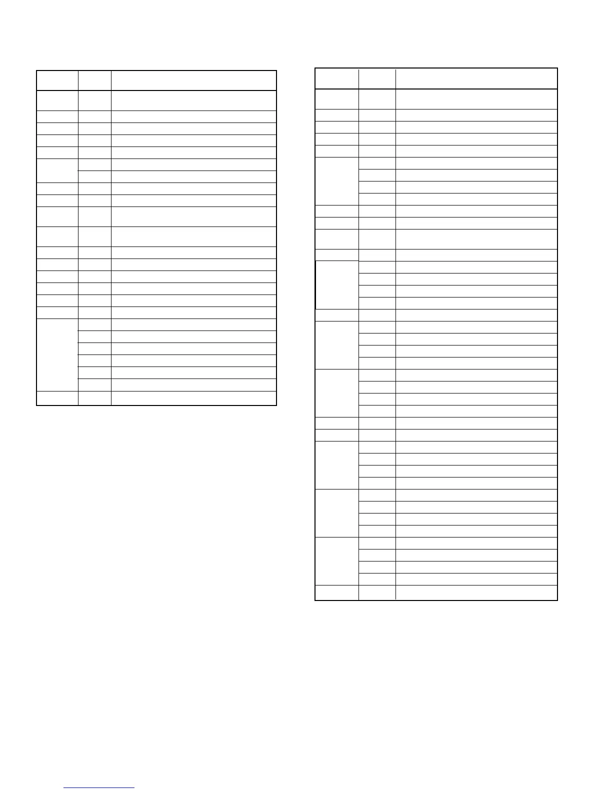
Table 14. Inputs and Outputs for Program UV4***
Units (Models AZ or AV/AH)
Software
Connection
Model
Component Description
IN0 All
Tenant override or remote spt. adjust or
both (optional)
IN1 All Room temperature sensor
IN2 All Discharge air temperature sensor
IN3 All Outdoor air temperature sensor
IN5 All Water-in temperature sensor
IN6
MDL07 Heating valve position
MDL08 F&BP damper position
IN7 All Outside air damper position
DI-2 All Day-night changeover device (optional)
DI-3 All
Ventilation lockout (default) or exhaust
fan interlock (optional)
DI-4 All
High pressure (HP) & low DX coil temp
(T4) switches
DI-5 All Low water coil temperature switch (T6)
RO-1 All Fan relay (R4)
RO-2 All Compressor relay (R1 on AZ, R7 on AV/AH)
RO-3 All Not used
RO-4 All Outside air damper open
RO-5 All Outside air damper close
RO-6
MDL07 Heating valve close (extend)
MDL08 F&BP damper close to face (extend)
RO-7
MDL07 Heating valve open (retract)
MDL08 F&BP damper open to face (retract)
RO-8
MDL07 Not used
MDL08 Heating EOC valve close (2-position, N.O.)
RO-10 All Exhaust fan relay or auxilliary heat relay
Software
Connection
Model
Component Description
IN0 All
Tenant override or remote spt. adjust or both
(optional)
IN1 All Room temperature sensor
IN2 All Discharge air temperature sensor
IN3 All Outdoor air temperature sensor
IN5 All Water-in temperature sensor
MDL09 Heating valve position
IN6
MDL10 F&BP damper position
MDL11 Heat/cool valve position
MDL12 F&BP damper position
IN7 All Outside air damper position
DI-2 All Day-night changeover device (optional)
DI-3 All
Ventilation lockout (default) or exhaust fan
interlock (optional)
DI-4 All Not used
MDL9 Not used
MDL10 Not used
MDL11 Low water coil temp switch (T6
MDL12 Not used
RO-1 All Fan relay (R4)
MDL09 Not used
RO-2
MDL10 Not used
MDL11 Heat/cool valve close (extend)
MDL12 Not used
MDL09 Not used
RO-3
MDL10 Not used
MDL11 Heat/cool valve open (retract)
MDL12 Not used
RO-4 All Outside air damper open
RO-5 All Outside air damper close
MDL09 Heating valve close (extend)
RO-6
MDL10 F&BP damper close to face (extend)
MDL11 Not used
MDL12 F&BP damper close to face (extend)
MDL09 Heating valve open (retract)
RO-7
MDL10 F&BP damper open to face (retract)
MDL11 Not used
MDL12 F&BP damper open to face (retract)
MDL09 Not used
RO-8
MDL10 Heating EOC valve close (2-postition, N.O.)
MDL11 Not used
MDL12 Heat/cool EOC valve close (2-postition, N.O.)
RO-10 All Exhaust fan relay or auxilliary heat relay
Notes:
1. Switch T6 is not installed on units with steam coils. These
units are wired to provide a constant, no-fault condition.
2. High pressure switch HP is not installed on AV/AH units.
Only low temperature switch T4 is connected to DI-14
on these units.
3. High pressure switch HP and low temperature switch
T4 are wired in series on AZ units only.
➁ ➂
➀
Notes:
1. Switch T6 is not installed on heating only units with steam
coils. Unit is wired to provide a constant, no-fault
condition.
Table 15. Inputs and Outputs for Program UV5***
Units (Models AV/AH) (2 pipe)
DI-5