IM 613 / Page 12 (Rev. 7/99)
4. Check that the conductors have been terminated at the unit
and the wall sensor package in accordance with the field
wiring diagram.
5. Check that the cable length between the wall sensor package
and its UVC does not exceed 250 feet.
6. 460V, Type AE & AZ Only: Check that 600-volt rated cable
has been used.
Network Communication (Master/Slave or MicroTech
Network Units)
1. Check that the cable is a twisted, shielded pair of
conductors.
2. Check that the shield is grounded in accordance with the
installation literature.
3. Check that the conductors have been terminated at the units
in accordance with the field wiring diagram.
4. At the UVC board, verify that the IDC connectors are
disconnected from the Comm A and Comm B ports.
(They will be connected during the start-up process.)
5. 460V, Type AE & AZ Only: Check that 600-volt rated cable
has been used.
6. MicroTech Network Units Only: Check that the conduc-
tors have been terminated at the Local Master Controller
(LMC) in accordance with the field wiring diagram supplied
with the LMC. Check that the cable length between the LMC
and the farthest UVC does not exceed 5000 feet.
Day-Night Changeover (Stand-alone or Master Units)
1. Check that the conductors have been terminated at the unit
in accordance with the field wiring diagram.
Note: Field terminations are not required for the factory-mounted
time clock and manual switch options.
2. Check that the ultimate changeover device provides the
proper action at the UVC. The dry contacts connected to
DI-2 must be “open for occupied” and “closed for
unoccupied.” If used, the factory-installed relay is wired so
that it must be “de-energized for occupied” and “energized
for unoccupied.”
3. 460V, Type AE & AZ Only: Check that 600-volt rated
conductors have been used.
Ventilation Lockout (Stand-alone, Master or Slave Units)
1. Check that the conductors have been terminated at the unit
in accordance with the field wiring diagram.
2. Check that the field-supplied device energizes the factory-
installed relay when ventilation lockout is desired.
3. 460V, Type AE & AZ Only: Check that 600-volt rated
conductors have been used.
Exhaust Fan Interlock
1. Check that the conductors have been terminated at the unit
in accordance with the field wiring diagram.
2. Check that the field-supplied device energizes the factory-
installed relay when exhaust fan interlock is desired.
3. 460V, Type AE & AZ Only: Check that 600-volt rated
conductors have been used.
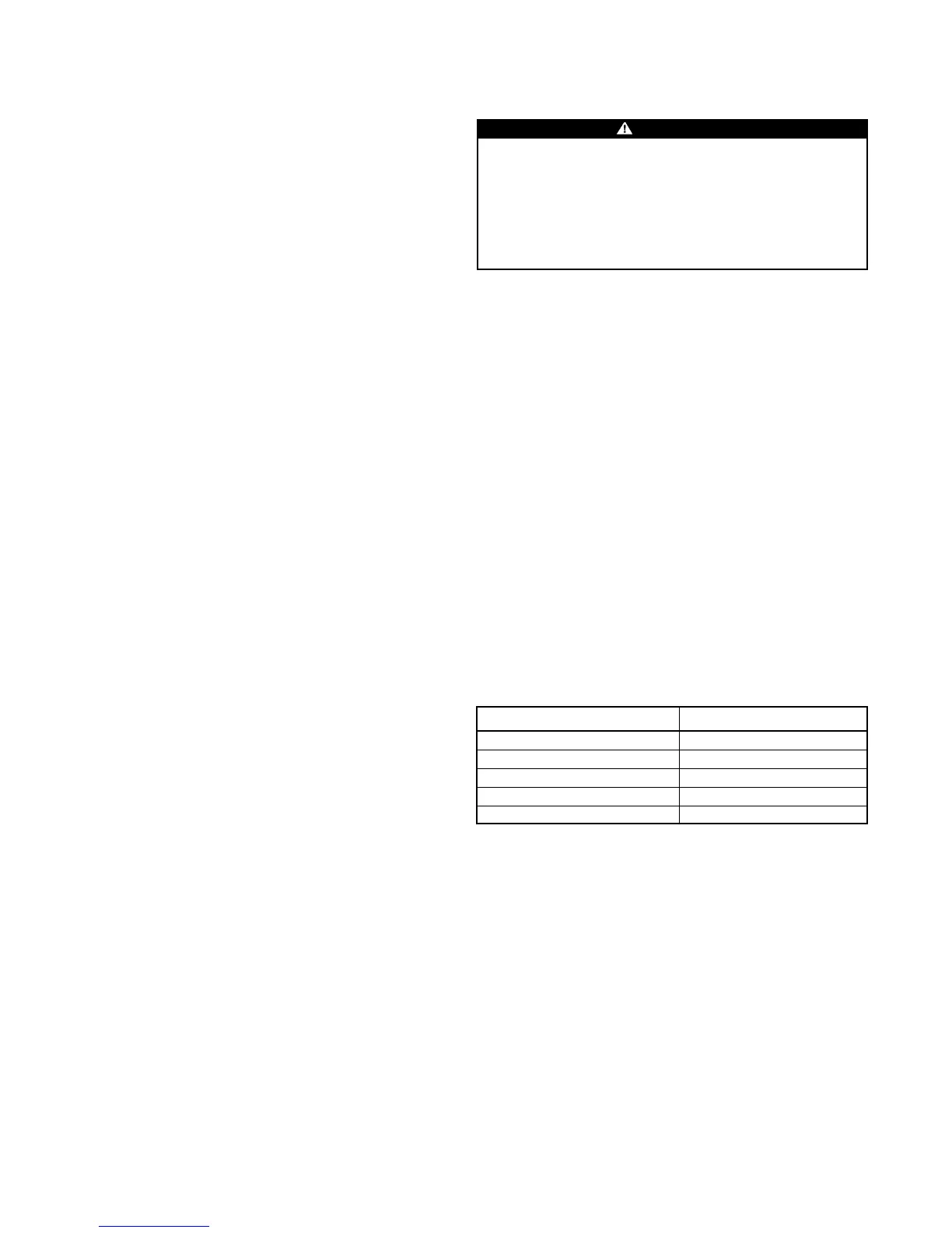
Setpoint Value
Occupied Cooling 78°F
Occupied Heating 72°F
Unoccupied Cooling 88°F
Unoccupied Heating 62°F
Minimum OA Damper Position 20%
Table 7. Network UVC Default Setpoints
Remote Condensing or Heat Pump Unit (AV/AH Units Only)
Check that the conductors have been terminated at the unit in
accordance with the field wiring diagram.
Setpoint Initialization
Stand-alone and Master/Slave Units
The heating setpoint, unoccupied offset, and minimum OA damper
position potentiometers (pots) should be set to the desired
settings prior to start-up. For more information, refer to “Setpoint
Adjustment Potentiometers” in the “Component Data” section of
this manual.
Note: In a master/slave application, the master’s pot
settings define the setpoint values for its slave controllers.
If communications fail, the affected slaves read their
setpoint values from their own setpoint pots. For this
reason, it is recommended that the three on-board setpoint
pots on each slave be set so that they match the master’s
settings.
Network Units
The three setpoint adjustment potentiometers on a network unit
are not operational. The UVC setpoint values are held in memory
and can only be modified over the MicroTech network. Initially,
before any changes are made over the network, the UVC will use
the default, factory-set setpoints shown in Table 7.
CAUTION
On AH units, it is recommended that the outdoor air
temperature sensor be located so that it will accurately sense
the outdoor air temperature. If this is not done, improper unit
operation or damage to the remote condensing or heat pump
unit could occur. The best location for the sensor is either
outside the building (shielded from solar radiation) or in the
outdoor air ductwork very near the intake.