Certified Drawing
IM 613 / Page 21 (Rev. 7/99)
Change Filter
The “Change Filter” fault is a network feature indicating that the
fan has operated longer than the set number of hours. Typically,
this alarm is used to alert the building operator of the need to
replace the filter. To clear the fault, the filter timer must be reset at
the network PC.
Effect:
• An alarm message Iis sent over the network.
Communication Error
The “Communication Error” fault can only occur on slave units. It
indicates that the unit is not communicating with its master. Refer
to “Test Procedures” in the “Service Information” section of this
manual for information on troubleshooting this fault.
Effects:
• Room temperature, unoccupied offset, and minimum
OA damper position setpoints will be obtained from
the slave UVC’s on-board pots.
• The operating mode will be that last received over
the network from the master (cycling power will place
the unit in the occupied mode).
• All other control processes execute normally.
Master UVC Connection Procedure
Normally, port Comm A of a master UVC is not available for any
use. The port may be reconfigured for PC communications at
9600 baud using the RS-232 format by performing the following
procedure:
1. Disconnect power to the UVC (use fan switch or main
power switch).
2. Set the hex switches to “FF.”
3. Connect the PC to the UVC at port Comm A.
4. Apply power to the UVC.
To return the master to normal operation, remove power, reset
the hex switches, disconnect the PC, and restore power.
Note: The above procedure will also reconfigure port Comm B.
As a result, network communications will be discontinued.
UVC Inputs and Outputs
IDC Terminal Connectors
All connections to the UVC board are made using 0.156"
insulation displacement type (IDC) terminals. The IDC
connectors can accept up to 18 AWG, 0.085" OD wire. They are
available in two- through six-conductor styles (see parts list).
The IDC connector displaces wire insulation to make
contact with the conductor. If a faulty UVC connection is
suspected, try pressing down on the wire in the IDC terminal with
a small screwdriver.
Analog Inputs
The UVC has 14 analog inputs. Ten of these are available for
external (IDC) connection; the remaining four are used for
internal connections to the three on-board pots and the
brownout voltage sensor.
The ten analog inputs that are available for external
connection are labeled “IN0” through “IN9” on the UVC and the
PC Connection
A personal computer (PC) equipped with the appropriate
Monitor software may be directly connected to any UVC.
Typically, for start-up or service purposes, the PC would be a
portable laptop or notebook type (see PC specification below).
For stand-alone, master, or slave controllers, the computer must
be loaded with “stand-alone” Monitor software. For network
controllers, the PC must be loaded with the job-specific “network”
Monitor software.
For all unit types, the PC is connected to the UVC at port Comm
A. For master UVC’s only, a special procedure is required to
reconfigure the port for PC connection (see below).
MicroTech controllers use the RS-232C format for PC
communications. The data transmission speed is 9600 baud.
PC Specification
A directly connected computer may be used for monitoring unit
operation, changing setpoints, trend logging, downloading soft-
ware, and diagnostics. The PC must be an IBM or 100% true
compatible with the following features (minimum requirements):
• 386SX microprocessor
• 2 Megabytes of RAM (Random Access Memory)
• 60 Megabyte hard disk drive
• 3˚” floppy disk drive
• Asynchronous Serial Communications Adapter
(9 or 25 pin male)
• 101 enhanced keyboard
• VGA graphics capability
• Internal time clock, battery backed
• Windows 3.1 or Windows 95
• MicroTech Monitor software
Cable Specification
A properly terminated, shielded, twisted pair cable is required to
connect a PC to the UVC (Belden 8761 or equivalent). The cable
must be terminated at an IDC connector as shown in Table 10.
The maximum allowable cable length for direct connection be-
tween the PC and UVC is 50 feet. If the desired length is over 50
feet, an RS-232 cable extension kit is required (contact AAF-
McQuay).
A universal communications cable kit that allows a PC to be
connected to any MicroTech controller is available from
AAF-McQuay. The part number is 57186801.
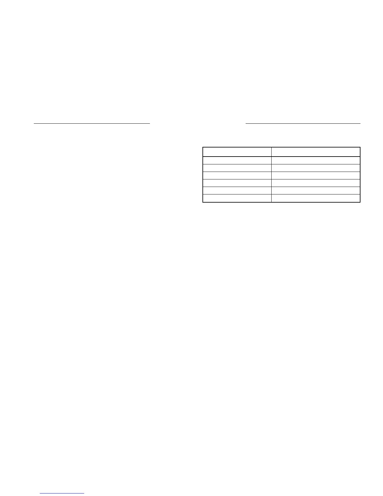
Comm. Port Terminal Connection
1 Jumped to terminal 2
2 Jumped to terminal 1
3 Transmit
4 Not used
5 Receive
6 Ground
Table 10. RS-232 Communications Cable Terminations
Service Information