IM 613 / Page 22 (Rev. 7/99)
Unit wiring diagram. Each input has two terminals: an “S” (signal)
terminal and a “G” (ground reference) terminal. Inputs IN0 and
IN1 have a common “G” terminal (see Figure 1). The “G”
terminals of inputs IN2 through IN9 are internally connected.
Each “S” terminal is internally connected to a 5 VDC power supply
through a 3.3 KW resistor. The voltage at the “S” terminal varies
as the temperature sensor resistance or actuator feedback signal
changes. The UVC converts these voltages into temperature or
actuator position data. (Refer to Table 18 and Figure 6.)
Digital Inputs
The UVC has six digital inputs, all of which are available for
external (IDC) connection. These inputs are labeled “DIGITAL
IN” on the UVC and “DI-0” through “DI-5” on the unit wiring
diagram. Each input has two terminals: a numeric terminal and a
common “DI-R” (ground) terminal (see Figure 1). All UVC digital
input circuits are optically isolated.
The digital inputs sense the presence or absence of an
external 24 VAC power source (transformer X3). The power source
is connected to the input through a switch or set of contacts (see
Figure 4). Refer to the wiring diagram supplied with your unit for
specific wiring details.
Figure 4. Digital Input Wiring Example
Relay Outputs
The UVC has eight relay outputs. These outputs are internally
connected to the normally open contacts of eight on-board,
electromechanical relays. The outputs are labeled “RELAY
OUTPUT” on the UVC and “RO-1” through “RO-8” on the unit
wiring diagram. Each output has two terminals: a numeric
terminal and a common “RO-H” (hot) terminal (see Figure 1).
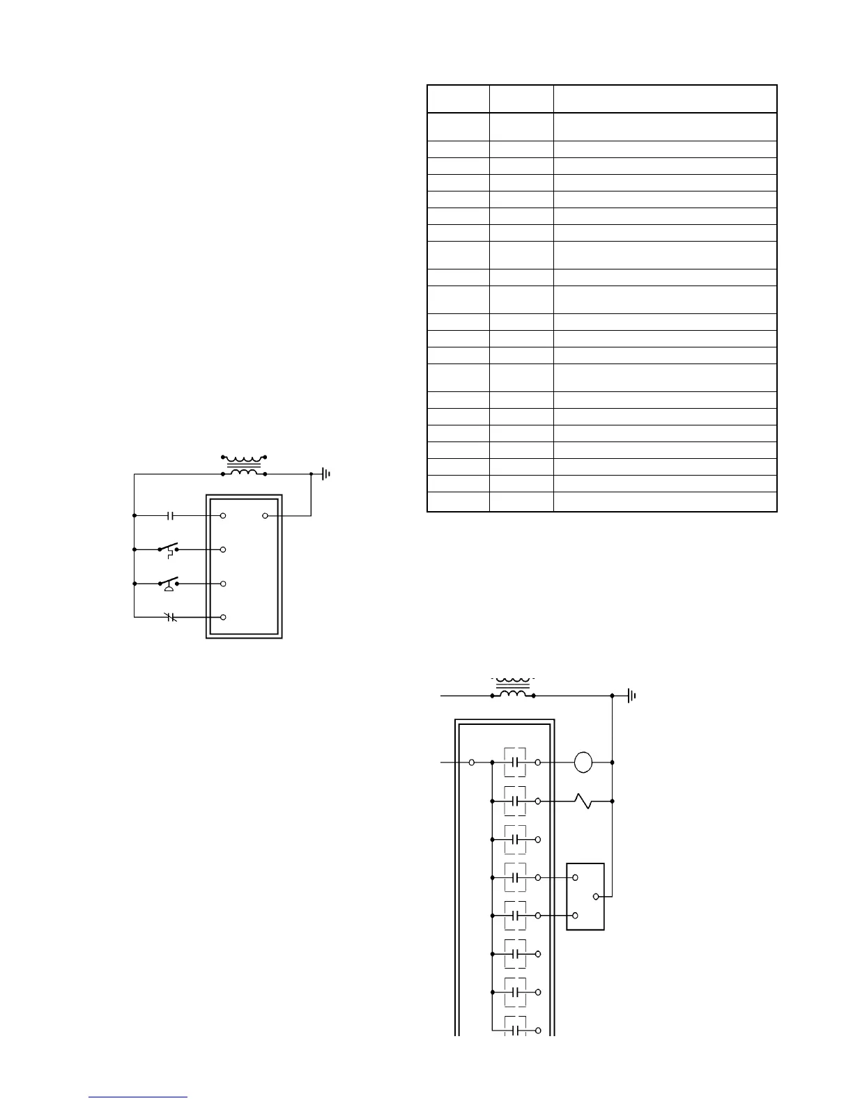
The unit ventilator’s 24 VAC loads are connected as shown in
Figure 5. The loads could be a contactor, another relay, a
solenoid or an actuator’s “open” or “close” circuits. Refer to the
wiring diagram supplied with your unit for specific wiring details.
Input/Output Tables
All UVC input and output connections and their corresponding
unit ventilator components are shown in the following tables. The
tables are arranged according to UVC program and software
model numbers. To determine the correct input/output
information for a particular unit ventilator, you must know these
numbers. Refer to the software ID tag attached to the UVC
faceplate, or refer to Table 4.
Connection
Software
Component Description
Model
IN0 MDL00
Tenant override or remote spt. adjust or
both (optional)
IN1 MDL00 Room temperature sensor
IN2 MDL00 Discharge air temperature sensor
IN3 MDL00 Outdoor air temperature sensor
IN5 MDL00 Not Used
IN6 MDL00 Not Used
IN7 MDL00 Outside air damper position
DI-1 MDL00
Ventilation lockout (default) or exhaust fan
interlock (optional)
DI-2 MDL00 Day-night changeover device (optional)
DI-3 MDL00
Emergency heat switch (SW5) & defrost
control (T5)
DI-4 MDL00 High pressure switch (HP)
DI-5 MDL00 Low DX coil temperature switch (T4)
RO-1 MDL00 Fan relay (R4)
RO-2 MDL00
Compressor relay
(R1 on AE, R7 on AV/AH)
RO-3 MDL00 Reversing valve
RO-4 MDL00 Outside air damper open
RO-5 MDL00 Outside air damper close
RO-6 MDL00 Electric heat stage 1
RO-7 MDL00 Electric heat stage 2
RO-8 MDL00 Electric heat stage 3
RO-10 MDL00 Exhaust fan relay or auxilliary heat relay
Figure 5. Relay Output Wiring Example
Notes:
1. Emergency heat switch SW5 and defrost control T5 are
wired in parallel. SW5 has momentary contacts and T5 has
maintained contacts.
2. High pressure switch HP is not installed on AV/AH units.
These units are wired to provide a constant, no-fault
condition.
➁
➀
UVC
RO-8
RO-7
RO-6
RO-5
RO-4
RO-3
RO-2
RO-1
X3
24 VAC
Relay
Solenoid
Modulating
Actuator
Open
Close
R0-H
Table 11. Inputs and Outputs for Program UV1***
Units (Models AE or AV/AH)
X3
24 VAC
DI-2
DI-R
DI-3
DI-4
DI-5
UVC