IM 613 / Page 28 (Rev. 7/99)
UVC Replacement
Data relating to the unit ventilator configuration and actuator
characteristics are stored at the factory when each unit is built
and tested. This information defines the program number,
software model, and several parameter settings that are
unique for each unit ventilator. If a UVC is defective and must
be replaced, its unit-specific software (defined by the above
data) must be loaded into the replacement controller.
If a PC is available, it may be possible to recover the software
from the defective UVC.
If a PC is not available or the software cannot be recovered,
the replacement UVC must be downloaded at the factory. To do
this, the factory needs the following information:
• Full model number
• Serial number
• Job control number
This information is listed on the unit mounted dataplate. It must
be included with the replacement UVC part order.
Note: If the linkage is disconnected or damaged, it is
possible that the actuator could extend beyond the nomi-
nal full stroke of one-half inch. If it does, the feedback
voltage could exceed the acceptable upper limit.
5. Remove the IDC connector from the analog input and
measure the DC voltage across the UVC terminals. It
should be approximately 5 VDC. If it is, the actuator is
defective. If it is not, the UVC is defective.
Note: Stroke endpoint parameters for each actuator are loaded
into the UVC at the factory and auto calibrated at each
power-up. If an actuator must be replaced, the stroke
endpoint parameters in the controller may need to be
reset. If nuisance alarms are occurring or if a valve or
damper will not fully close, obtain factory service.
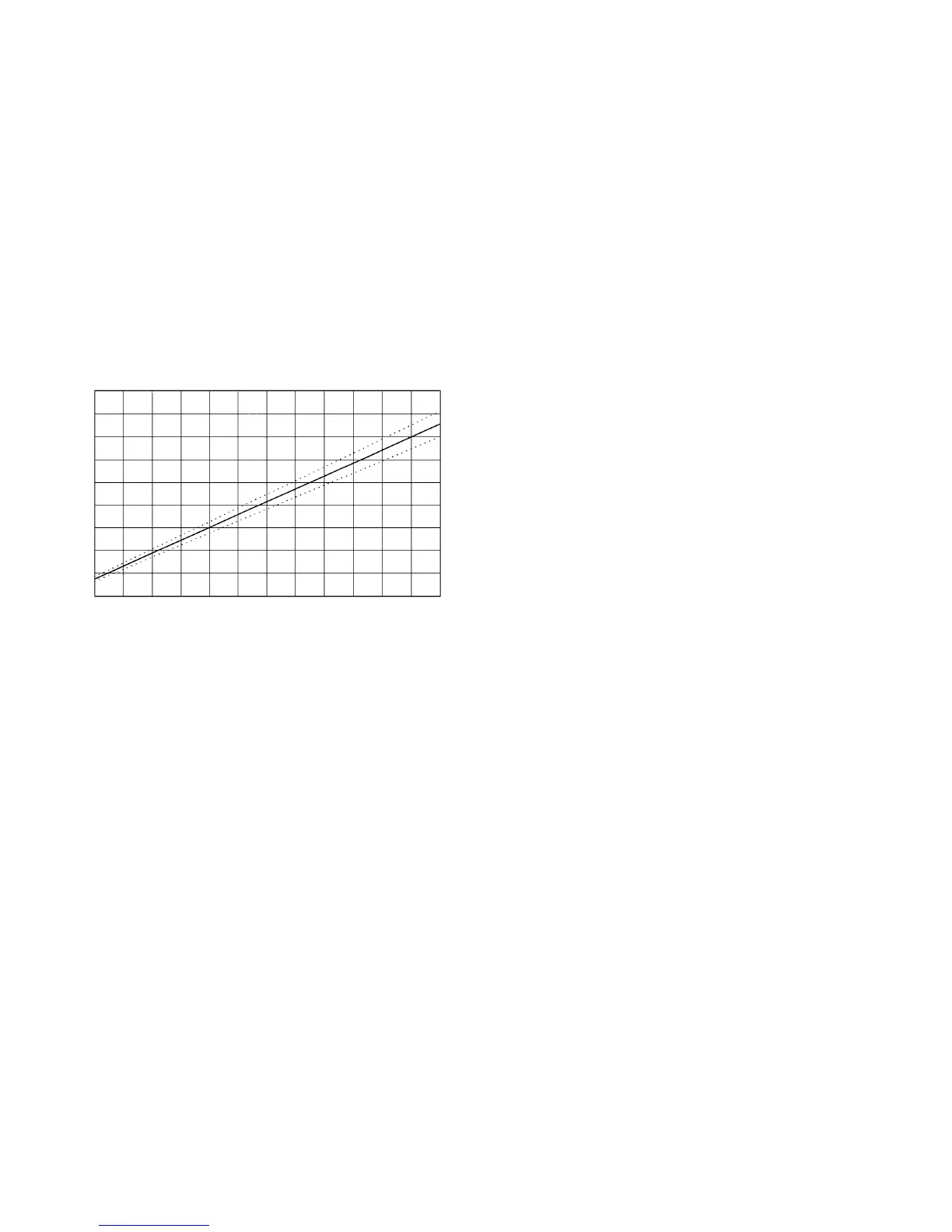
Figure 6. Barber-Colman Actuator Position Feedback Voltages
Notes:
1. Extension percentage is based on
1
/2-inch nominal full
stroke.
2. Voltages are measured at UVC analog input terminals.
3. Range of expected accuracy is defined by the dotted lines.
4. Voltage at maximum possible actuator extension is 4.63
VDC (linkage disconnected).
Master/Slave Communication Error Fault
A master/slave communication error is indicated by a 16-blink
fault code. Troubleshooting this fault is limited to the following
checks:
• Verification of master and slave UVC communication port
voltages
• Verification of communications wiring integrity
• Verification of network addressing
The best way to accomplish these checks is to perform the
master/slave start-up procedure. Refer to “Master/Slave” in the
“Start-up” section of this manual.
If all of the above checks have been performed and the UVC
will still not communicate, either the controller is defective or
factory service is required.
0.0 0.4 0.8 1.2 1.6 2.0 2.4 2.8 3.2 3.6 4.0 4.4 4.8
160
140
120
100
80
60
40
20
0
-20
Actuator Extension (%)
Voltage (VDC)