ESG‐InvM
25
Part4 ‐ Control
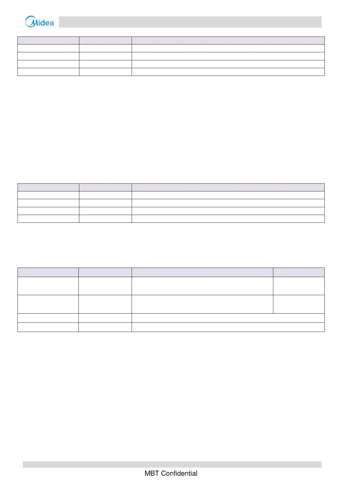
Forcoolingmode:
Component Wiringdiagramlabel Controlfunctionsandstates
Invertercompressor COMP Runsatoilreturnoperationrotationspeed
DCfanmotor FAN Controlledaccordingtocoolingmode
Electronicexpansionvalve EXV 304(steps)
Four‐wayvalve 4‐WAY Off
5.2 DefrostingOperation
• Normaldefrosting
Inordertorecoverheatingcapacity,thedefrostingoperationisconductedwhentheoutdoorunitairsideheatexchanger
isperformingasacondenser.Thedefrostingoperationiscontrolledaccordingtooutdoorambienttemperature,airside
heatexchangerrefrigerantoutlettemperatureandthecompressorrunningtime.
• Manualdefrosting
Itcanbeactivebysettingonthewiredcontroller,whichisalsoaimedtohelpheatpumprecoverheatingcapacityquickly.
Manualdefrostingfunctionwillbedeactivatedautomaticallyafternormaldefrosting.
Component Wiringdiagramlabel Controlfunctionsandstates
Invertercompressor COMP Runsatdefrostingoperationrotationspeed
DCfanmotor FAN Off
Electronicexpansionvalve EXV Fullyopen
Four‐wayvalve 4‐WAY Off
5.3 SmartGridfunction
The grid will provide two signals(EVU, SG) to indicate the grid load. Heat pump with Smart Grid function can identify
differentsignalscombinationandadjustworkingstatetoadapttothegridload.WiththehelpofSmartGridfunction,heat
pumpwillgiveprioritytousecleanenergyasmuchaspossibletoachieveenergysavingandcarbonreduction.
EVUsignal SGsignal Heatingcontrol Coolingcontrol
ON ON
Boostheatingmode
(Heatingcapacityenhancedcomparedtonormalheatingmode)
Normaloperation
ON OFF
Boostheatingmode
(Heatingcapacityenhancedcomparedtonormalheatingmode)
Normaloperation
OFF ON Normaloperation
OFF OFF Heatpumprunsforcertaintimeandthenturnsoff.

 Loading...


