Part 5 – Diagnosis and Troubleshooting
5.27 Inverter module Troubles shooting for single-phase models
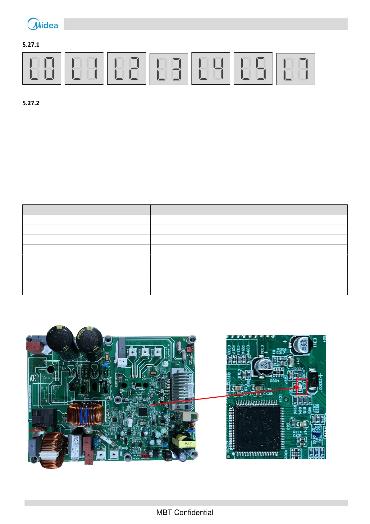
Digital display output
Description
L0 indicates Inverter or compressor protection
L1 indicates DC bus low voltage protection
L2 indicates DC bus high voltage protection
L3 indicates current sampling error of PFC circuit
L4 indicates rotating stall protection
L5 indicates zero speed protection
L7 indicates phase loss protection of compressor
The specific error codes can also be obtained from the LED indicators on the inverter module.
LED1 flashing pattern (RED)
Flashes 1 times and stops for 0.4s, then repeats
L0 indicates Inverter or compressor protection(overcurrent)
Flashes 2 times and stops for 0.4s, then repeats
L0 indicates Inverter or compressor protection(overheated)
Flashes 3 times and stops for 0.4s, then repeats
L1 indicates DC bus low voltage protection
Flashes 3 times and stops for 0.4s, then repeats
L2 indicates DC bus high voltage protection
Flashes 4 times and stops for 0.4s, then repeats
L3 indicates current sampling error of PFC circuit
Flashes 5 times and stops for 0.4s, then repeats
L4 indicates rotating stall protection
Flashes 5 times and stops for 0.4s, then repeats
L5 indicates zero speed protection
Flashes 6 times and stops for 0.4s, then repeats
L7 indicates phase loss protection of compressor
LED location of inverter module

 Loading...


