Midea ESG-Inv M Series Pool Heat Pump Manual
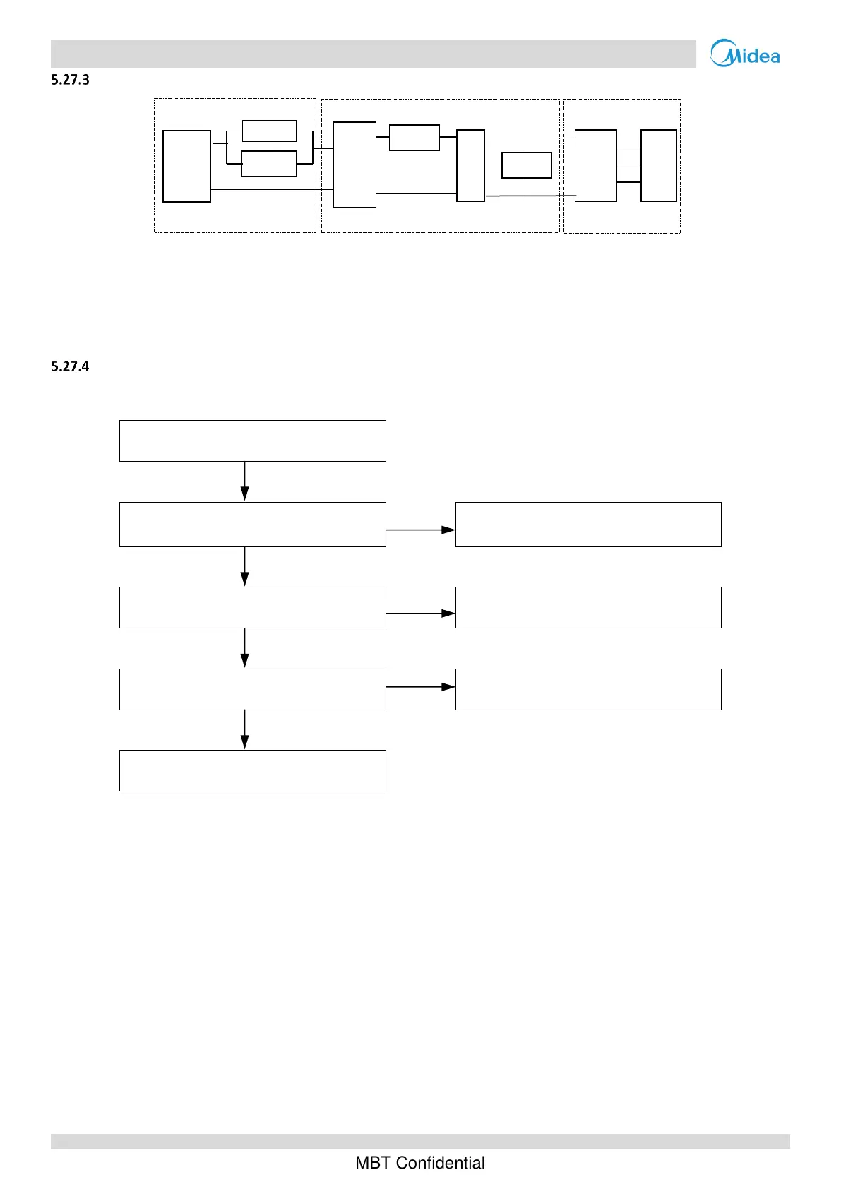
Principle of DC inverter
①Contactor is open, the current across the PTC to charge capacitor. After 5 seconds, the contactor closed.
②220-240V AC power supply change to DC power supply after bridge rectifier.
③The capacitor output steady power supply for inverter module P N terminals. In standby the voltage between P and N
terminal on inverter module is 1.4 time of AC power supply. When the fan motor is running, the voltage is 380V DC.
L0/L4 troubleshooting
Situation 1: L0 or L4 error appears immediately after the compressor starts up
U V W wire between inverter module and
compressor is not connected properly
1
Ensure U V W wire is connected properly
Inverter module is damaged
2
Replace the inverter module
3
Compressor has malfunctioned
4
Replace the outdoor unit main PCB
Notes:
1. Connect the U V W wire from the inverter module to the correct compressor terminals, as indicated by the labels on the compressor.
2. Measure the resistance between each of U, V and W and each of P and N on the inverter module. All the resistances should be infinite. If any of them are
not infinite, the inverter module is damaged and should be replaced.
3. When replacing an inverter module, a layer of thermally conductive silica gel should be painted on the IPM module, IGBT, diode brigde rectifer (on the
reverse side of the inverter module PCB).

 Loading...


