Part 5 – Diagnosis and Troubleshooting
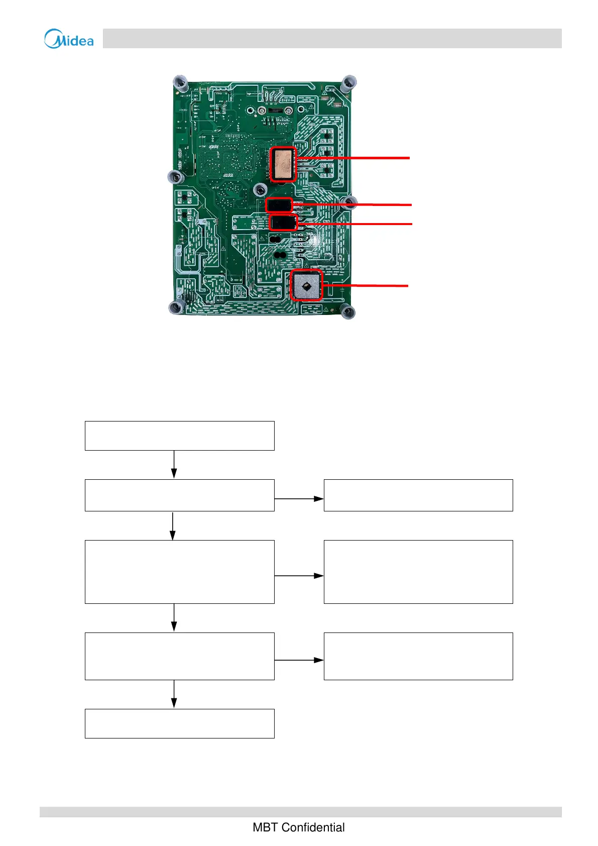
IPM
IGBT
Diode
Brigde rectifier
4. The normal resistances of the inverter compressor are 0.7-1.5Ω among U V W and infinite between each of U V W and ground. If any of the resistances differ
from these specifications, the compressor has malfunctioned.
Situation 2: L0 or L4 error appears after the compressor has been running for a period of time and the compressor
speed is over 60rps
DIP Switch S1 setting is wrong
Refer to the wiring diagram to reset the
S1 setting
LED1 flashes 2 times and stops for 0.4s,
then repeats(Inverter module has
overheated)
Repaint the thermally conductie silica
gel on the IPM module, IGBT, diode,
brigde rectifer (on the reverse side of
the inverter module PCB)
LED1 flashes 1 times and stops for 0.4s,
then repeats(Inverter module is over-
current
1
)
Replace the inverter module
2
Notes:
1. Use clip-on ammeter to measure the compressor current, if the current is normal indicates the inverter module is failed, if the current is abnormal indicates
the compressor is failed.
2. When replacing an inverter module, a layer of thermally conductive silica gel should be painted on the PFC and IPM modules (on the reverse side of the
inverter module PCB).

 Loading...


