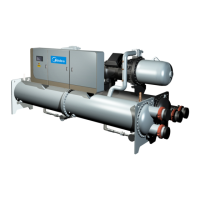
Flooded type water cooled screw chiller (PCB Control) MCAC-CTSM-2012-11
70
changed (if necessary) after the initial 2000 hours of compressor operation. Oil line pressure loss is
monitored by the control and reported for each compressor as the oil filter pressure drop.
Normally the pressure differential (discharge pressure minus oil pressure) is typically less than 150kPa
for a system with clean internal and external filters. To determine the oil pressure drop due to the oil lines
and external filter only, connect a gage to the oil pressure bleed port. Compare this value to the
discharge pressure read at the touch screen. If this value exceeds 150 kPa, replace the external filter.
Compressor Change out Sequence
Compressor service requires metric tools and hardware. Change compressors according to the following
procedure:
Compressor removal procedure
1) Cut off all main and control circuit power supply of the machine.
2) Close the discharge valve, suction valve, and evaporator inlet line service angle valve, oil line shutoff
valve for circuit to be changed. Disconnect the oil inlet line from the compressor.
3) Remove any remaining refrigerant in the compressor and refrigerant lines by proper reclaiming
devices. All of the refrigerant that is in the evaporator must be removed if there is no suction service
valve installed on the evaporator.
IMPORTANT: Cooling and chilled water pumps must be energized. There must be water flowing through
heat exchangers whenever adding or removing charge.
4) Remove junction box cover of compressor to be changed. Check main power leads for marked
numbers. If no numbers are visible on leads, mark leads with appropriate numbers to match those
printed on the ends of the terminal lugs. This is extremely important as power leads MUST be installed
on the exact terminals from which they were removed.
5) Disconnect main power leads from compressor terminal lugs. Mark remaining control circuit wires
(connected together with wire nuts) for ease of reconnecting later.
6) Remove the capacity adjustment SV and oil solenoid valve and high-pressure switch from
compressor.
Caution: The next steps involve compressor unbolting and removal. Compressor seals are made using
O-rings. Use care when removing bolts and disconnecting flanges. The O-rings must NOT be re-used.
New O-rings are provided with the replacement compressor. Be sure that an appropriate lifting cart or
hoist is used to avoid injury.
7) See Fig. 31 for lifting methods of screw compressor. Make sure compressor is properly rigged
before unbolting. Move lifting apparatus into place and attach to the 2 lifting rings on the compressor.
When lifting the compressor, it is recommended to use a steel chain or steel cable as shown in the figure
below, and also a safety rope can also be used provided it has loading capacity of 2000kgf. Make sure
that the chains, cables, ropes or other lifting equipment are properly positioned so as to avoid damage to
compressor or its accessories. Keep the compressor in horizontal position when lifting, and avoid the
compressor to crash or fall on the ground; hit the wall or any other event that may damage it or its