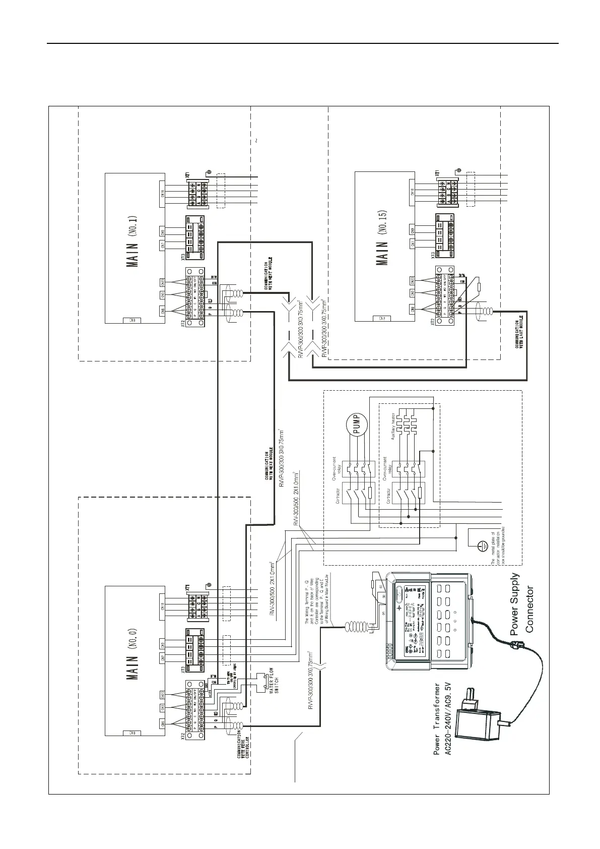
Attached Drawing (II) Networking Communication Schematic of Main Unit and
Auxiliary Unit
A B
C
N
H 2 P 1 P 2H 1
T h e l e n gth o f w i r e
s h o u l d b e s h o rte r
t h a n 5 0 0 m
100Ω
Black
Yellow
Gray
Quer y
Fault
N o t e s
The w iring d i a g ram o f a u x iliary h eater a n d
pum p is j u s t for r e fe r ence ,plea s e f o l l o w th e
in s truc t i o n s o f c o rresp onding a u x iliary
h e a ter p r o d u c ts.
P leas e c h oose s u c h a cce s s o r y a s p o w er
wire , s w itc h o f a u x iliary h e a ter a c c o r d ing t o
th e actu a l p aram e t e r o f p ro d u c t s a n d n a t i ona l
H 2 P 1 P 2H 1
H 2 P 1 P 2H 1
120Ω
RVV-300/500 4X10+1X6mm
2
RVV-300/500 4X10+1X6mm
2
RVV-300/500 4X10+1X6mm
2
POWER 380V 3N 50Hz
POWER 380V 3N~
50Hz
POWER 380V 3N~50Hz
POWER 380V 3N~50Hz
 Loading...