5.4 MGBT-F120W/RN1
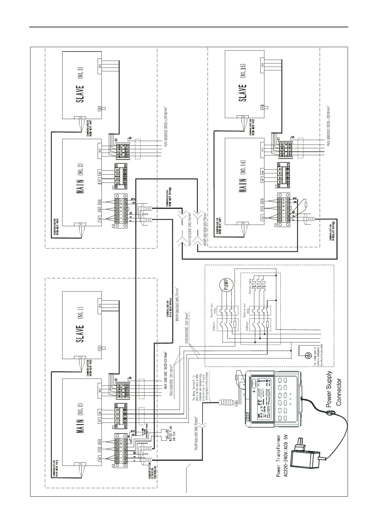
Attached Drawing (II) Networking Communication Schematic of Main Unit and
Auxiliary Unit
A B
C
N
H2 P1 P 2H1
The length of wire
shoul d b e shorter
than 500 m
100Ω
Black
Yellow
Gray
Query
Fault
Notes
The wiring diagram of auxiliary heater and
pump is just for reference ,please fo llow the
instructions of corresponding auxiliary
heater products.
Please choose such accessory as power
wire , switch of auxiliary heater according to
the actual parameter of products and national
H2 P 1 P 2H1
H2 P 1 P 2H1
120Ω
POWER 380-415V 3N~50Hz
POWER 380-415V 3N~50Hz
POWER 380-415V 3N~50Hz
POWER 380-415V 3N~50Hz
 Loading...