R410A All DC Inverter V4+S Series 60Hz MCAC-VTSM-2015-09
110 Installation
Note: Air outlet could not be installed on the lifting part; otherwise water shall be discharged to ceiling or could not be discharged.
5.5 Overflow water test and water pass test
5.5.1 Overflow water test
After finishing the construction of drainage pipe system, fill the pipe with water for 24 hours to check for
leakage at joints.
5.5.2 Water pass test
1. Natural drainage mode
Fill condensation pan with above 600ml of water slowly through check port, check drainage outlet for water
discharge.
2. Pump drainage mode
1) Remove water level switch plug, remove water-finding cover and slowly fill condensation pan with about
2000ml of water through water-finding port to avoid touching the drainage pump motor.
2) Power on and let the air conditioner operate in cooling mode. Check operation status of drainage pump, and
then turn on water level switch, check operation sound of pump and transparent hard pipe at drainage outlet to
confirm water is being discharged. (Depending on the length of drainage pipe, water shall be discharged after
about a 1 minute delay.)
3) Stop the operation of air conditioner and return water-finding cover to its original place.
a. After shutting down the air conditioner, wait for three minutes and check for abnormalities. If drainage pipe
was not installed properly, back-flow water will trigger the alarm on the remote control receiver board and
water will return to the condensation pan.
b. Add water until reaching alarm water level, ensure the drainage pump can discharge water in a timely
fashion. If water level does not decline within 3 minutes of reaching the warning level, it will cause shutdown of
unit. When this situation occurs, normal startup shall be carried out after turning off power supply and removing
the accumulated water.
Note: Drain plug at the main condensation pan is used for removing accumulated water when maintaining air conditioner. During
normal operation, the drain should be plugged to prevent leakage.
6. Duct engineering
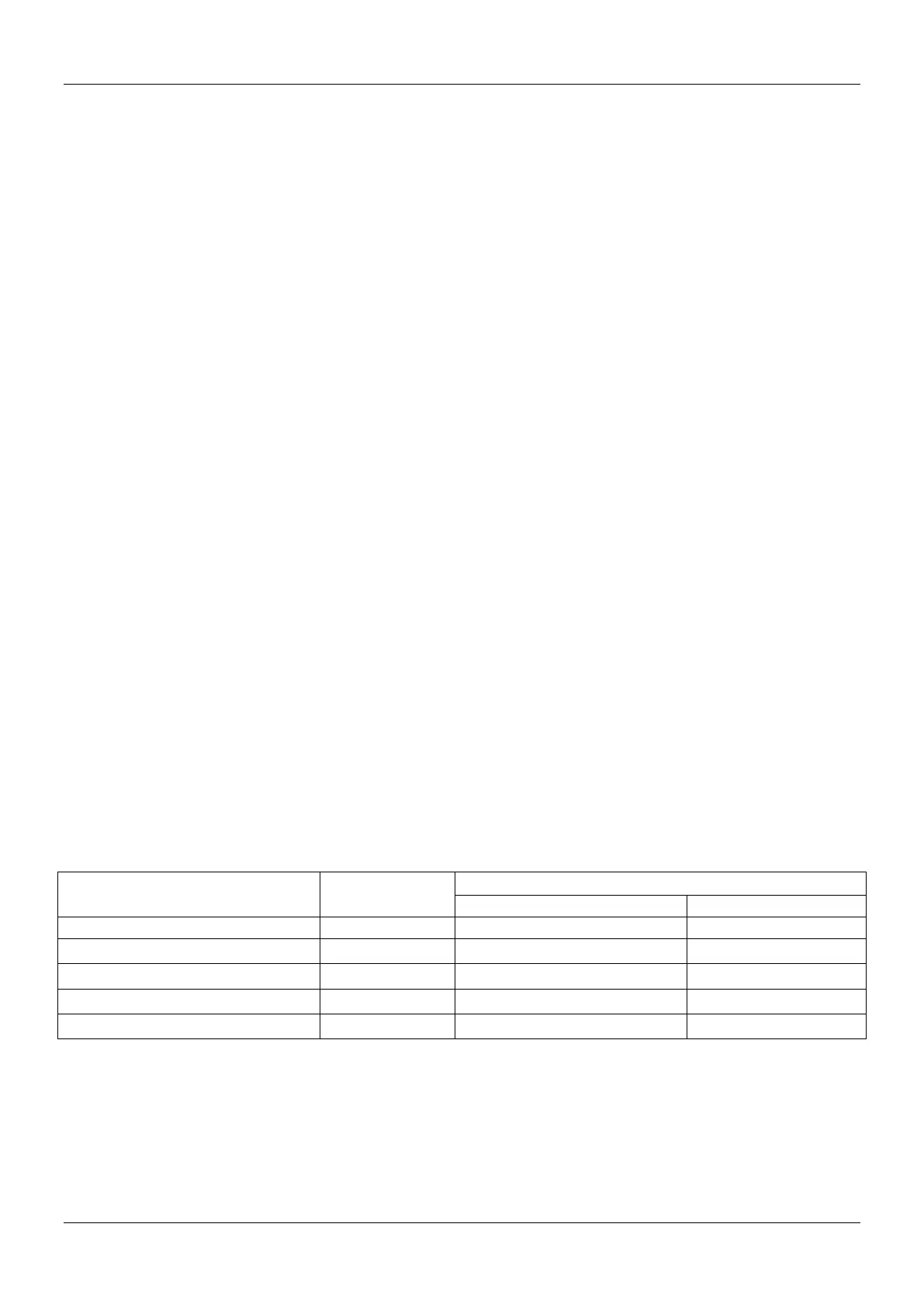
6.1 Duct selection
1. The material, specifications, performance and thickness of metal duct should be in accordance with the
relevant local regulations and standards. Sheet metal thickness should not be less than the regulations in the
table below:
Thickness of steel sheet duct
Diameter(D) or edge length (b) of duct
(in.(mm))
Middle/low pressure system
12-19/32(320)<D(b)≤17-23/32(450)
17-23/32(450)<D(b)≤24-51/64(630)
24-51/64(630)<D(b)≤39-3/8(1000)
2. The material, specifications, performance and thickness of non-metal duct should be in compliance with
design and local regulations..
3. The body, frame, fixing material and sealed cushion of fire-proof air duct should be made of
non-combustible materials. Its fire resistance rating should be in accordance with the design requirement.
4. The sheathing of composite duct should be made of non-combustible materials. Inner insulation material
should be fireproof or fire retardant with a B1 rating.
5. The permitted deviation to outer diameter or long edge of duct: when less than 11-13/16”(300mm), it is