MCAC-VTSM-2015-09 R410A All DC Inverter V4+S Series 60Hz
Troubleshooting 129
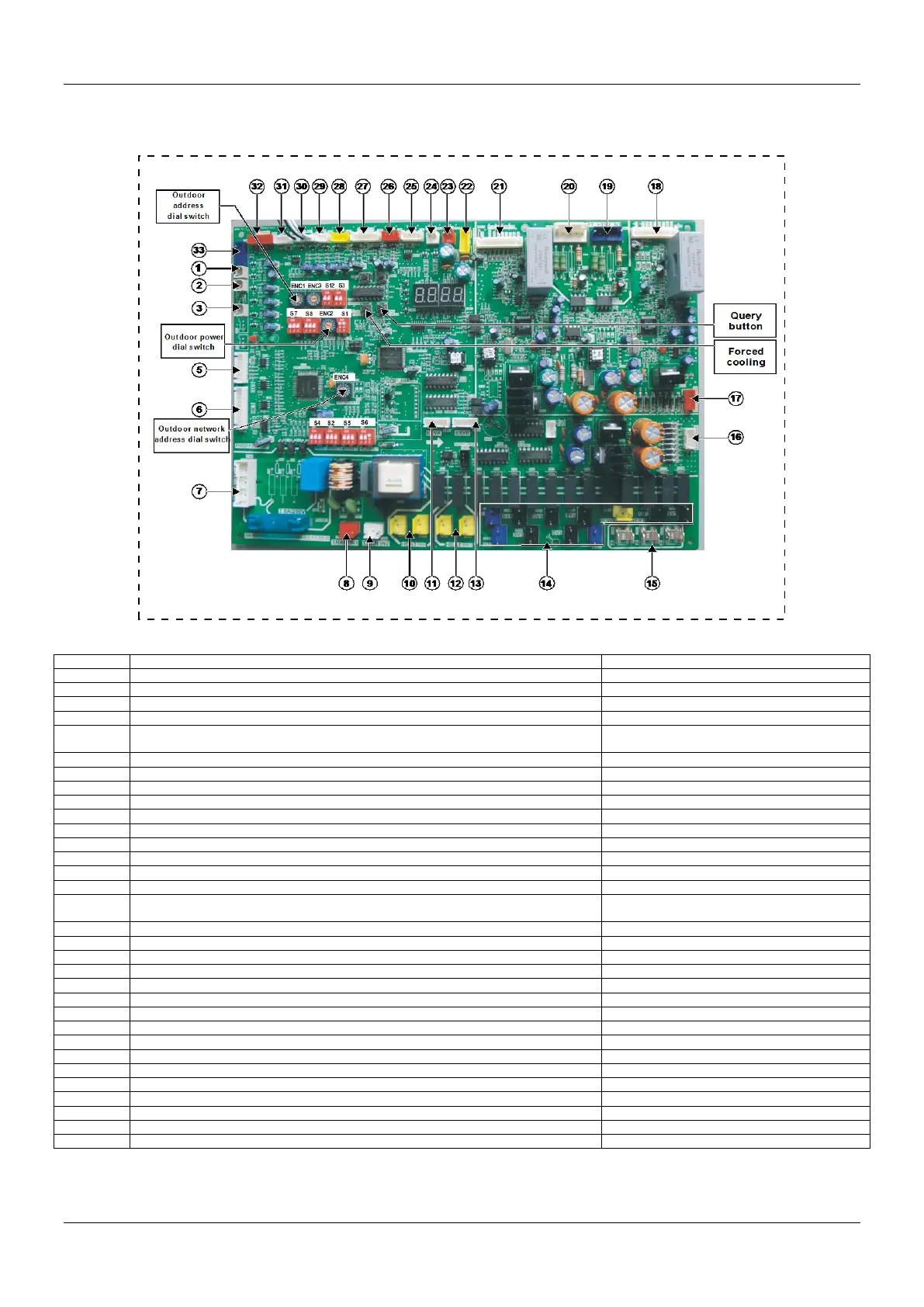
1. Outdoor main control board instructions
1.1 Main PCB ports instructions
Outdoor main PCB ports instructions
Discharge temperature detection port of inverter compressor A
DC0~5V (in dynamic change)
Discharge temperature detection port of inverter compressor A or B
DC0~5V (in dynamic change)
Temperature detection port of heat sink
DC0~5V (in dynamic change)
Wiring port for communication between indoor and outdoor units, indoor unit network,
outdoor unit network and network accounting
Power input of No.1 transformer
Power input of No.2 transformer
The first pin on the left: DC 12V
The first pin on the left: DC 12V
Power output of No.1 transformer
Yellow-Yellow: AC 9V; Brown-Brown: AC 13.5V
Power output of No.2 transformer
Yellow-Yellow: AC 14.5V; Blue-Blue:
16V
Activation port of inverter module B
The third pin on the left: DC3.3V
Voltage detection port of inverter module B
Voltage detection port of inverter module A
Activation port of inverter module A
The third pin on the left: DC3.3V
Power supply port of main PCB
ON/OFF signal input port for system low pressure detection
ON/OFF signal input port for system high pressure detection
Current detection port of inverter compressor A and B
AC0~7.8V (in dynamic change)
Input port for system high pressure detection
DC0~5V (in dynamic change)
Outdoor ambient temperature and condenser temperature detection port
DC0~5V (in dynamic change)
Outdoor units communication port
The first pin on the left: DC5V
The first pin on the left: DC5V

 Loading...


