V4+R VRF 50/60Hz
201702 27
5 Normal Operation Control
5.1 Component Control During Normal Operation
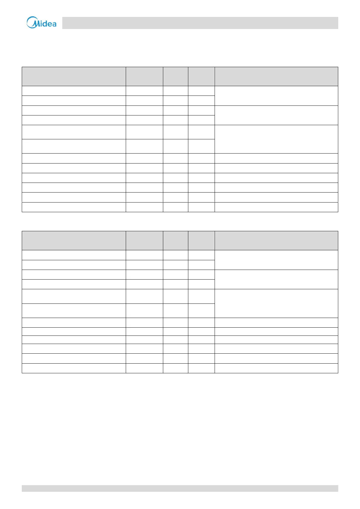
Table 3-5.1: Component control during normal cooling operation
Control functions and states
Controlled according to load requirement
Controlled according to discharge pressure
Electronic expansion valve A
Position (steps) from 0 (fully closed) to 480 (fully
open), controlled according to discharge
temperature
Electronic expansion valve B
Solenoid valve (liquid refrigerant injection)
Only open if discharge temperature > 100
o
C
Solenoid valve (oil balance)
Solenoid valve (fast defrosting)
Table 3-5.2: Component control during heating operation
Control functions and states
Controlled according to load requirement
Controlled according to outdoor heat exchanger pipe
temperature
Electronic expansion valve A
Position (steps) from 0 (fully closed) to 480 (fully
open), controlled according to discharge superheat
Electronic expansion valve B
Solenoid valve (liquid refrigerant injection)
Only open if discharge temperature > 100
o
C
Solenoid valve (oil balance)
Solenoid valve (fast defrosting)
Open during defrosting operation
5.2 Compressor Output Control
The compressor rotation speed is controlled according to the load requirement. Before compressor startup, the outdoor
units first estimate the indoor unit load requirement according to the nominal capacity of indoor units currently running,
and then correct for ambient temperature. The compressors then start up according to the corrected load requirement.
During operation the compressors are controlled according to the nominal capacity of indoor units currently running and
the indoor unit heat exchanger temperatures. If the actual load requirement can be provided by one unit alone, then only
one unit starts up. If the actual load requirement requires all outdoor unit modules to operate, the weighted average
actual load requirement is sent to each module and each module operates according to this distributed load
requirement.