V4+R VRF 50/60Hz
66 201608
Midea V4+R Series Service Manual
Procedure 4.9.4
Power supply for main PCB and
transformer is abnormal
1
Provide normal power supply
The transformer has malfunctioned
2
There is a source of electromagnetic
radiation near the unit, such as
high-frequency transmitter or other high
strength radiation device
Remove the source of interference
Notes:
1. Measure the voltages of ports CN31, CN33 and CN35 on the main PCB (labeled 8, 9 and 24, respectively, in Figure 5-2.1 in Part 5, 2.1 “Ports”). The normal
voltage between CN31 and CN33 terminals is 220V, between GND and the 5V pins of CN35 is 5V, between GND and 12V pins of CN35 is 12V. If one or more
of the voltages are not normal, the power supply for main PCB and transformer is abnormal.
2. Measure the voltages of ports CN32 and CN34 on the main PCB (labeled 18 and 19, respectively, in Figure 5-2.1 in Part 5, 2.1 “Ports”). The normal voltage
across the upper two pins of CN32 is 13.5V (AC), across the lower two pins is 9V (AC). The normal voltage across the upper two pins of CN34 is 14.5V (AC),
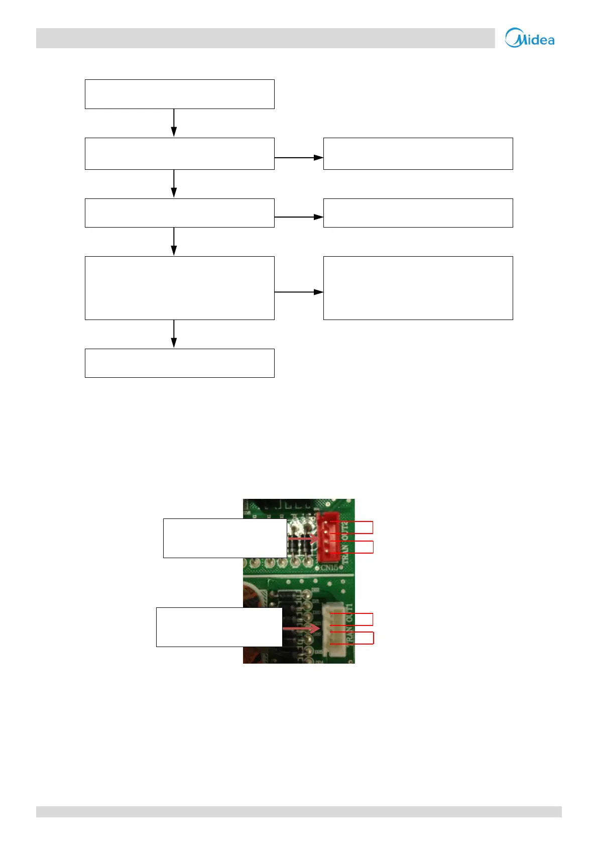
across the lower two pins is 14.5V (AC). If one or more of the voltages are not normal, the transformer has malfunctioned. Refer to Figure 5-4.2.
Figure 5-4.2: Transformer power output terminals
CN34: No.2 transformer
power output
CN32: No.1 transformer
power output