V4+R VRF 50/60Hz
96 201608
Midea V4+R Series Service Manual
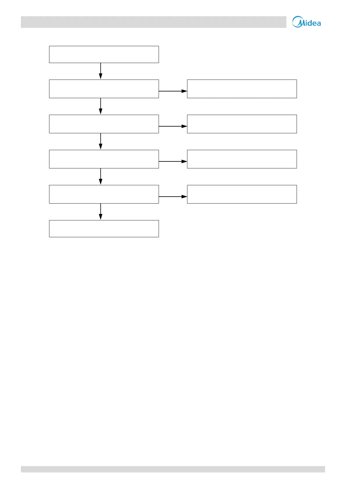
Procedure 4.21.4
The inverter module heat sink is blocked
or dirty
1
Clean or replace the heat sink
The screws connecting the heat sink to
the inverter module are loose
2
Tighten the screws and make sure the
heat sink is well-connected
Inverter module temperature sensor
connection on main PCB is loose
3
Ensure the sensor is connected properly
Inverter module temperature sensor has
short circuited or failed
4
Notes:
1. Refer to Figures 5-1.1 and 5-1.3 in Part 5, 1 “Outdoor Unit Electric Control Box Layout”.
2. Refer to Figures 5-1.1 and 5-1.3 in Part 5, 1 “Outdoor Unit Electric Control Box Layout”.
3. Inverter module temperature sensor connection is port CN4 on the main PCB (labeled 3 in Figure 5-2.1 in Part 5, 2.2 “Ports”).
4. Measure sensor resistance. If the resistance is too low, the sensor has short-circuited. If the resistance is not consistent with the sensor’s resistance
characteristics table, the sensor has failed. Refer to Figures 5-1.1 and 5-1.3 in Part 5, 1 “Outdoor Unit Electric Control Box Layout” and to Table 5-5.3 in Part
5, 5.1 “Temperature Sensor Resistance Characteristics”.