V4+R VRF 50/60Hz
60 201608
Midea V4+R Series Service Manual
Procedure 4.6.4
ODU power supply voltage is not within
±10% of rated voltage or a phase is
missing
1
Provide normal power supply
Wires between outdoor main PCB, AC
filter boards and electric control box
power supply terminals are loose
2
Ensure the wires are connected properly
High voltage circuit error has occurred,
such as the compressor has
malfunctioned
3
, the fan motor has
short-circuited
4
, or the inverter module
has short-circuited
5
Replace or repair the relevant parts
Notes:
1. The normal voltage between A and N, B and N, and C and N is 198-242V.
2. Refer to Figures 5-1.1 to 5-1.4 in Part 5, 1 “Outdoor Unit Electric Control Box Layout” and to the V4+R Engineering Data Book, Part 2, 5 “Wiring Diagrams”.
3. The normal resistances of the inverter compressor are 0.7-1.5Ω among U V W and infinite between each of U V W and ground. If any of the resistances
differ from these specifications, the compressor has malfunctioned. Refer to Figures 5-4.6 and 5-4.7 in Part 5, 4.19.6 “xL0 troubleshooting”.
4. The normal resistances of the fan motor coil among U V W are less than 10Ω. If a measured resistance is 0Ω, the fan motor has short-circuited. Refer to
Part 2, 1 “Layout of Functional Components”.
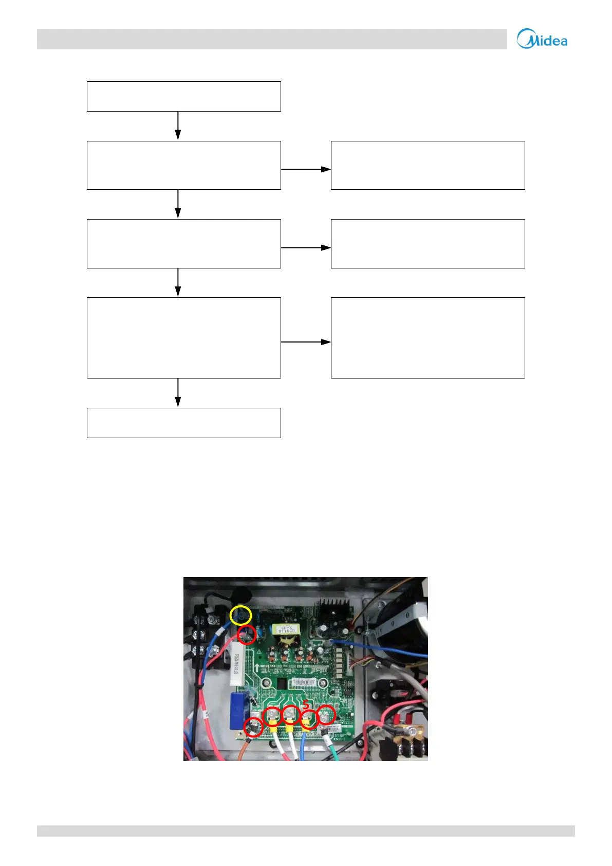
5. Set a multi-meter to buzzer mode and test any two terminals of P N and U V W of the inverter module. If the buzzer sounds, the inverter module has
short-circuited. Refer to Figures 5-1.1 and 5-1.3 in Part 5, 1 “Outdoor Unit Electric Control Box Layout” and to Figure 5-4.1.
Figure 5-4.1: Inverter module terminals
 Loading...


